Methods and systems for viewing geometry of an object model generated by a CAD tool

a technology of object model and computer aided design, applied in the field of computer graphics, can solve the problems of limiting the design review activity, high-speed graphic work stations are often expensive, and generally not purchased, and achieve the effect of reducing the cost of high-speed graphic workstations and reducing the cost of high-speed graphics

Inactive Publication Date: 2006-03-30
THE BOEING CO
View PDF1 Cites 175 Cited by
  • Summary
  • Abstract
  • Description
  • Claims
  • Application Information

AI Technical Summary

Benefits of technology

[0005] Methods, systems, and articles of manufacture consistent with the present invention allow one or more users on respective client computer systems on a network to col...

Problems solved by technology

But high-speed graphic work stations often are expensive and generally not purchased by a user for project employees other than design engine...

Method used


Image

  • Methods and systems for viewing geometry of an object model generated by a CAD tool
  • Methods and systems for viewing geometry of an object model generated by a CAD tool
  • Methods and systems for viewing geometry of an object model generated by a CAD tool

Examples


Embodiment Construction

[0033] Reference now will be made in detail to an implementation in accordance with methods, systems, and products consistent with the present invention as illustrated in the accompanying drawings. The same reference numbers may be used throughout the drawings and the following description to refer to the same or like parts.

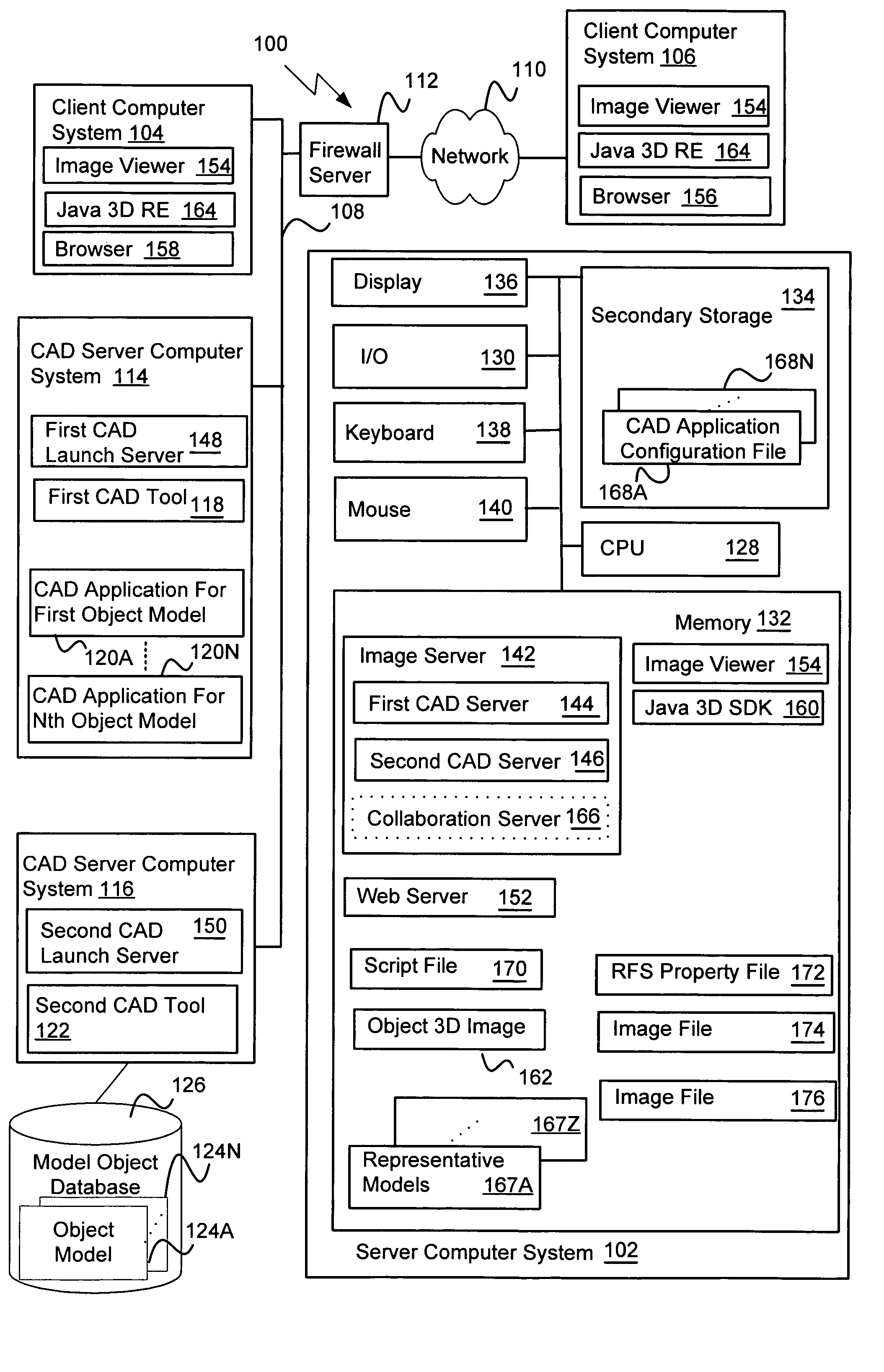
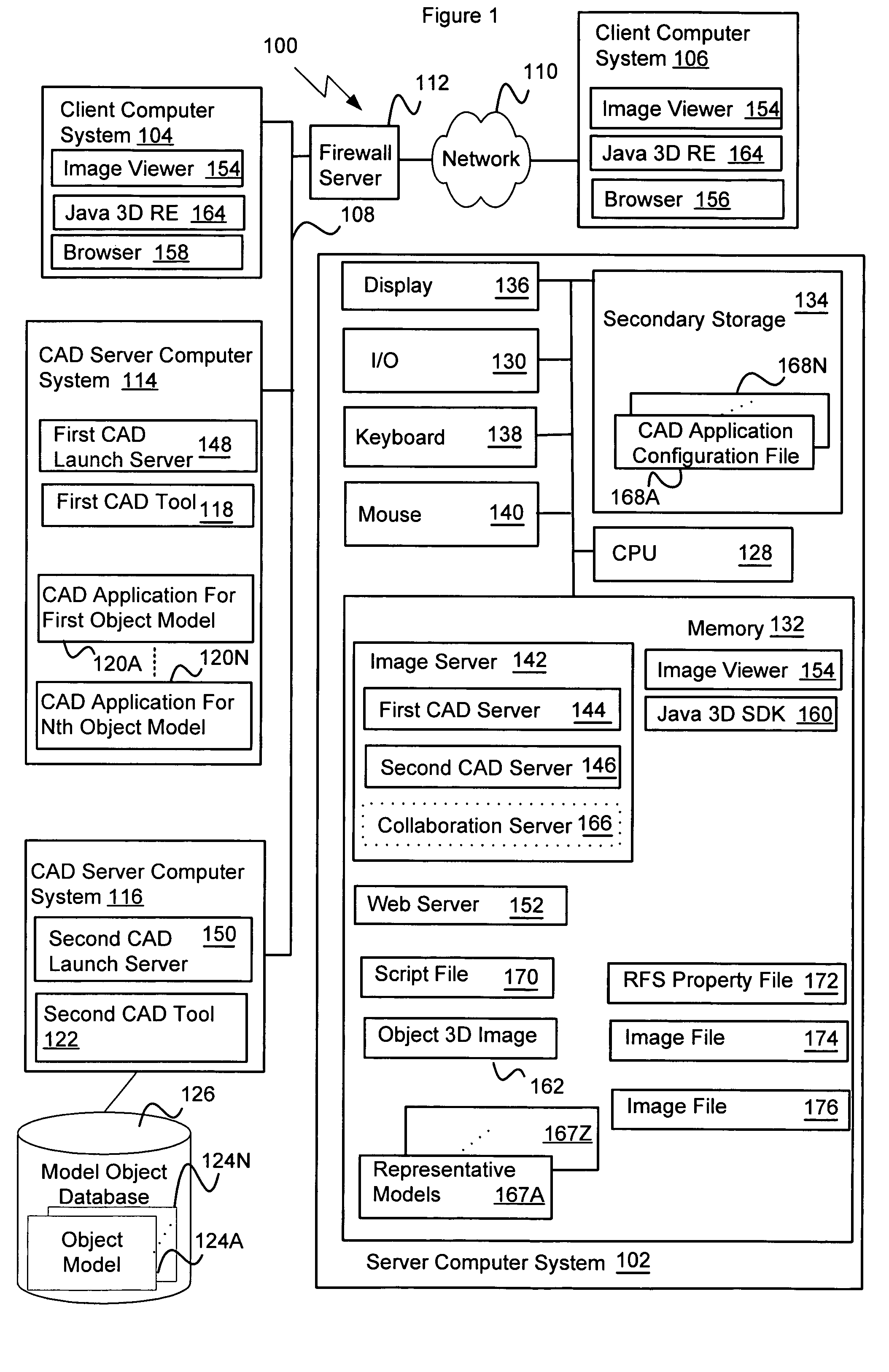
[0034]FIG. 1 depicts a block diagram of a data processing system 100 suitable for allowing a user to remotely view, alone or collaboratively with other users, geometry of an object model generated by a CAD tool consistent with the present invention. The data processing system 100 includes a server computer system 102 and one or more client computer systems 104 and 106. In the implementation shown in FIG. 1, the server computer system 102 is operatively connected to the first client computer system 104 via an internal network 108 and to the second client computer system 106 via an external network 110 and a commercially available firewall server 112. The server c...


PUM


Abstract

A system for remotely viewing geometry of an object model generated by a CAD tool hosted on a server computer on a network. The system has an image viewer accessible via a client computer on the network and an image server operatively connected between the image viewer and the CAD tool. The system receives an object model selection, provides the CAD tool with an ICAD application associated with the selection, commands the CAD tool to generate an object model having one or more elements using the ICAD application, displays on the client computer a structure identifying the one or more elements, receives a request to view a selected element, commands the CAD tool to generate an image file describing geometry of the selected element in response to the request, and displays the geometry of the selected element on the client computer in accordance with the image file.

Description

BACKGROUND OF THE INVENTION [0001] The present invention relates to computer graphics, and more particularly, to methods and systems for viewing three-dimensional (3-D) geometry of an object model generated by a computer aided design (CAD) tool. [0002] Engineers use conventional CAD applications or systems to design and visualize an object, such as a building, a car, an airplane (and its respective components or elements), in three dimensions (3-D). The CAD systems often use hundreds of thousands of polygons (e.g., triangles in a three-vector coordinate system) to represent the geometry of the object, such as surfaces, volumes, or elements of the object, in 3-D scenes for display on a video terminal. The 3-D scenes typically are generated using multiple two-dimensional computer images representing a corresponding portion of the geometry of the object and together reflect a cubic volume of the object. CAD systems often allow the user to change his viewpoint or change the geometry in ...

Claims


Application Information

Patent Timeline
IPC IPC(8): G06T15/00
CPCG06T2200/16G06T19/20G06T2219/2021G06T2219/2012G06T2219/2016G06T2200/24
Inventor IODICE, ARTHUR P.GINGRICH, CHARLES M.MCGOEY, PAUL
Owner THE BOEING CO
Why Eureka
Try Eureka