
Diffuse photon map decomposition for parallelization of global illumination algorithm

a global illumination and decomposition technology, applied in the field of computer graphics, can solve the problems of computational cost and difficulty in efficiently searching the kd-tree of a single large set of photons, and achieve the effect of reducing the cost of image processing and improving the efficiency of search

Inactive Publication Date: 2006-03-30
INTEL CORP
View PDF2 Cites 35 Cited by
  • Summary
  • Abstract
  • Description
  • Claims
  • Application Information

AI Technical Summary

Benefits of technology

The invention is about a computer graphics technique called photon mapping, which uses a single list of photons to capture global illumination. The technique involves creating a kd-tree to organize the photons and their associated data. The process of selecting control points, estimating illumination at those points, and creating a kd-tree for each control point is described in detail. The invention aims to improve the efficiency and accuracy of photon mapping for computer graphics rendering.

Problems solved by technology

Creating a kd-tree for a single large set of photons (e.g., a kd-tree of tens of millions of photons) may be computationally expensive and difficult to efficiently search.
Accordingly, such a kd-tree may become a bottleneck for processing purposes.

Method used


Image

  • Diffuse photon map decomposition for parallelization of global illumination algorithm
  • Diffuse photon map decomposition for parallelization of global illumination algorithm
  • Diffuse photon map decomposition for parallelization of global illumination algorithm

Examples


Embodiment Construction

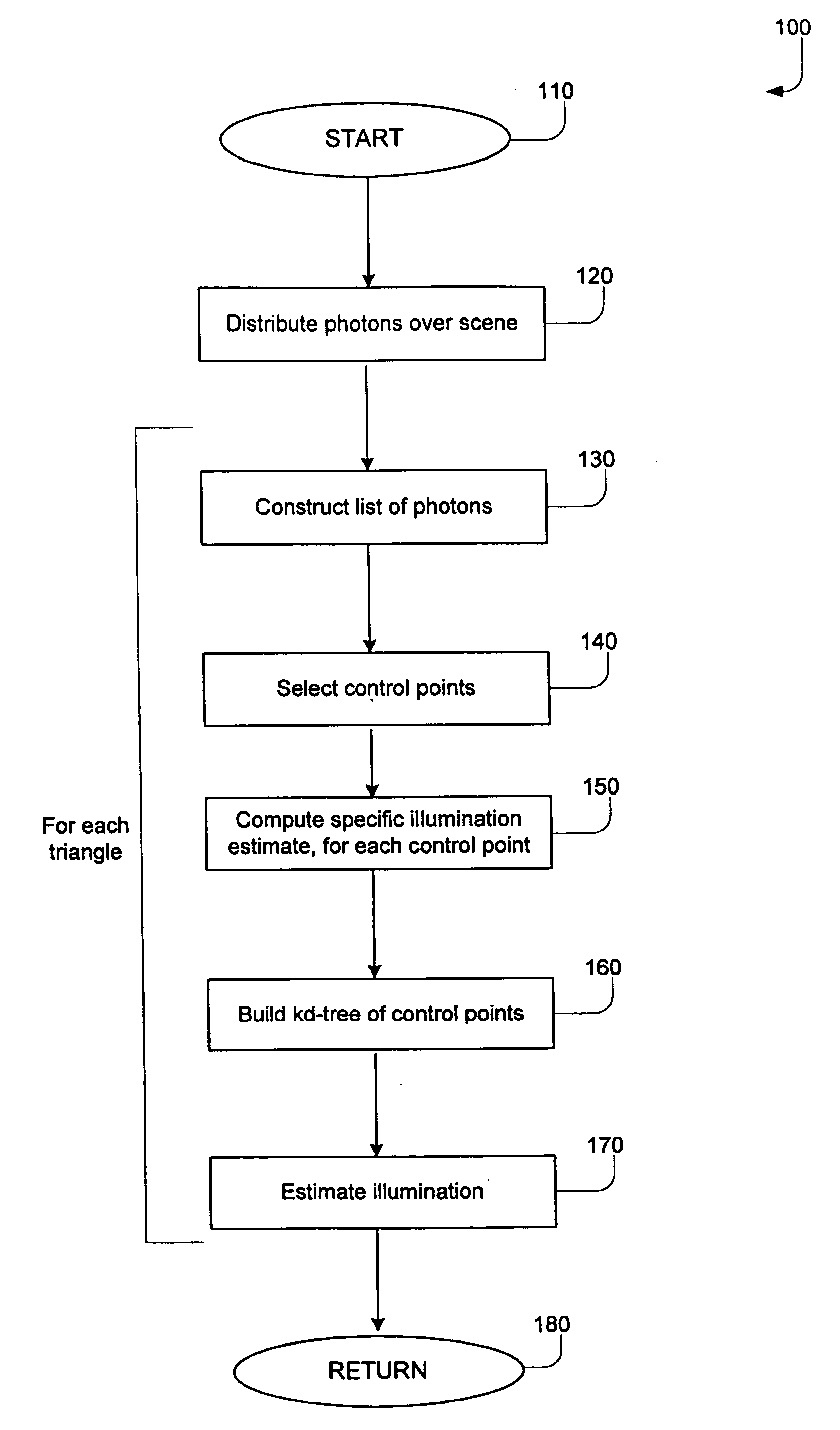
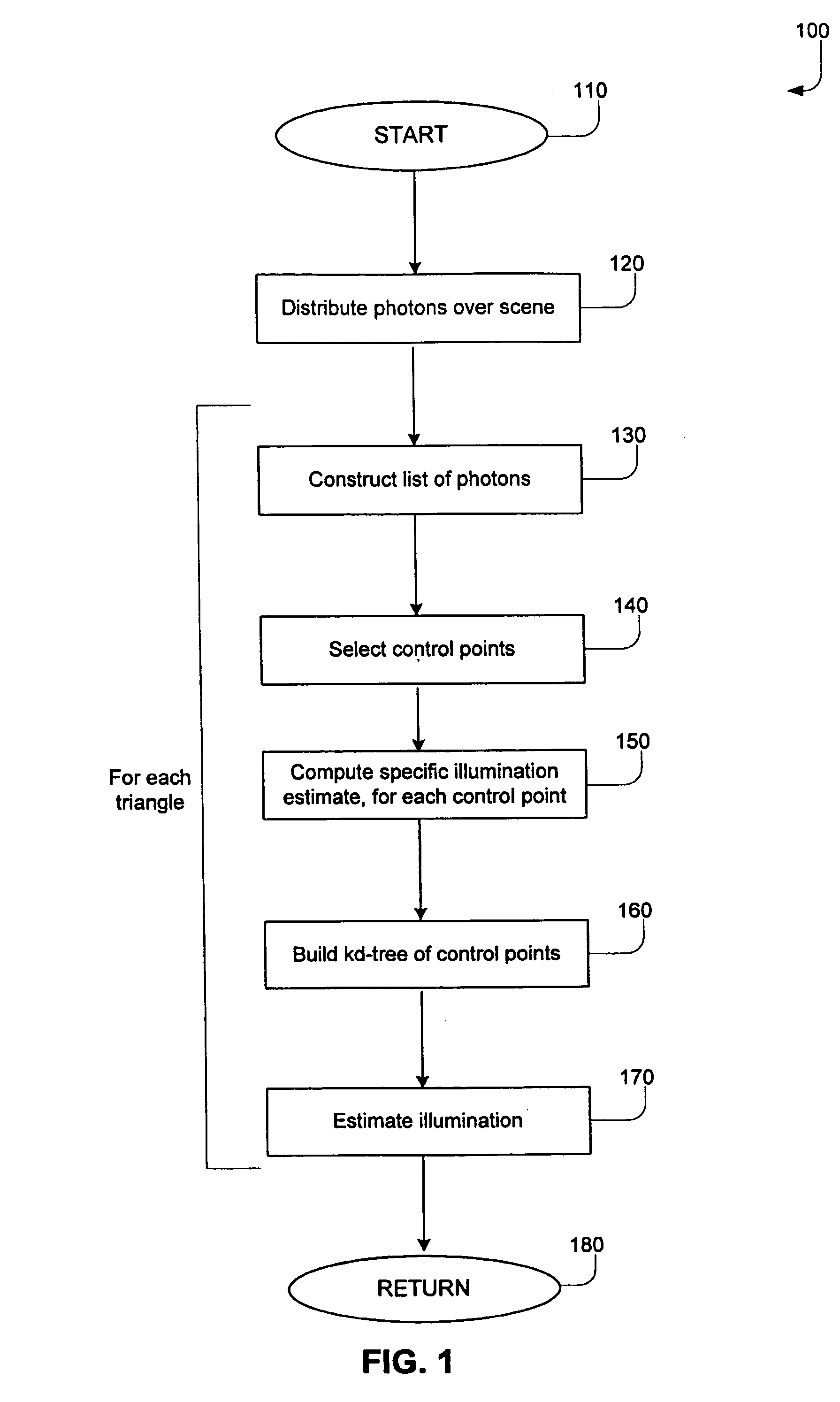
[0016]FIG. 1 illustrates the overall processing of an embodiment of the invention. The process may begin at block 110. In block 120, photons may be distributed over the scene to be rendered. Given that a scene may be rendered as a set of triangles, blocks 130 through 170 of FIG. 1 may be performed for each triangle or for each of a subset of the triangles. In block 130, a list of photons may be constructed for a triangle. In block 140, control points within the triangle may be selected. A control point is a reference point for a neighborhood or region of the triangle. The illumination at the control point will be estimated. This will allow the estimation of illumination at other points in the region. The selection and role of control points will be described further below. In block 150, the specific illumination estimate may be constructed for each of one or more control points in the triangle. In block 160, a kd-tree of the control points may be built. In block 170, illumination ma...


PUM


Abstract

A given computer graphics scene may be rendered as a set of triangles. A set of photons may be distributed over the scene, and a number of steps may be performed for each triangle. For each triangle, a list of photons may be constructed. For that triangle, a set of control points may be identified for purposes of determining global illumination. For each control point, a specific illumination estimate may be computed. A kd-tree of the control points of the triangle may be built. An illumination estimate may then be drive for the triangle.

Description

BACKGROUND OF THE INVENTION [0001] Some embodiments of the invention described may relate to computer graphics, and in particular, to illumination. [0002] Stated generally, computer graphics rendering is a process by which graphics instructions and data are received and processed so that image data is produced. This image data may then be sent to an input / output device (I / O) such as a display. Rendering creates data that may be displayed as an image. The resulting image (or set of resulting images) that is displayed in aggregate at a given point in time is known as a scene. A scene represents a computer rendering of what a camera or viewer might see at a given moment in time. [0003] Rendering may include a number of processes, one of which is ray tracing. In ray tracing, the path taken by a ray of light through a scene may be traced, as the ray undergoes reflection, refraction, and / or absorption whenever it touches an object in the scene. For example, given a light source, a ray of ...

Claims


Application Information

Patent Timeline
Patent Type & Authority Applications(United States)
IPC IPC(8): G06T15/50G06T15/60
CPCG06T15/506G06T15/06
Inventor SEVASTIANOV, IGORSOUPIKOV, ALEXEI M.RESHETOV, ALEXANDER V.
Owner INTEL CORP
Learn More