Electronic camera having light-emitting unit

a technology of light-emitting unit and electronic camera, which is applied in the field of electronic cameras, can solve the problems of user losing a shooting chance and shooting with under exposur

Active Publication Date: 2006-03-30
CASIO COMPUTER CO LTD
View PDF3 Cites 73 Cited by
  • Summary
  • Abstract
  • Description
  • Claims
  • Application Information

AI Technical Summary

Problems solved by technology

Along charging time of the capacitor increases a shooting interval, and as a result, the user often loses a shooting chance.
In this kind of camera, since its flashmatic unit automatically sets the guide number (GN) determined on the assumption that the capacitor is charged completely, an error in guide number can cause an error in aperture value which is determined based on the guide number and the distance to the object, resulting shooting with under exposure.

Method used


Image

  • Electronic camera having light-emitting unit
  • Electronic camera having light-emitting unit
  • Electronic camera having light-emitting unit

Examples


first modification

[First Modification]

[0158] In the present modified embodiment, a detecting unit 35 is provided outside the image pick-up element 30 to detect color temperature information. The present embodiment employs a so-called an external light measuring system, but in not limited to this external system. The modified embodiment can employ an internal light measuring system, which detects color temperature information from difference in color signals separated by the color-component separating circuit 56.

[0159] As shown in FIG. 20, the present modified embodiment can employ a system having a spectrophotometer 70 for precisely measuring a color temperature of light from the light source other than the external or internal light measuring system shown in FIG. 19.

[0160] The arrangement having the spectrophotometer 70 is provided with a slit 71, diffraction grating 72, and optical distributing unit 73.

[0161] The slit 71 is a plate like member with a fine slit formed therein, into which slit lig...

second modification

[Second Modification]

[0184] In the present second modification, plural light-emitting members 40 of the flashlight emitting device 26 are separately switched to emit light as illustrated in FIG. 24, whereby the light-emitting position or the light-emitting angle is changed during the strobe-light angle bracket photography. The strobe-light angle bracket photography is not limited to the above arrangement, but some number of the light-emitting members 40 of the flashlight emitting device 26 may selectively be switched to emit light as illustrated in FIG. 25.

[0185] Meanwhile, the number and positions of the light-emitting members 40 which emit light may be changed or switched for the strobe-light angle bracket photography, as illustrated in FIG. 26. As described above, one release operation by the user can correct the light-emitting angle as well as light-emitting amount of the flashlight emitting device 26, whereby it is possible to increase opportunities to obtain image of desired ...

third embodiment

[0186] The light-emitting members 40 of the light-emitting unit 38 disposed in the horizontal direction emit light, whereby the strobe-light angle bracket photographing operation is performed with side illumination. In the present third modification, the strobe-light angle bracket photographing operation may be performed under illumination in the vertical direction by turning the camera by 90 degrees, that is, the strobe-light angle bracket photographing operation may be performed under illumination of ascending or descending vertical angles.

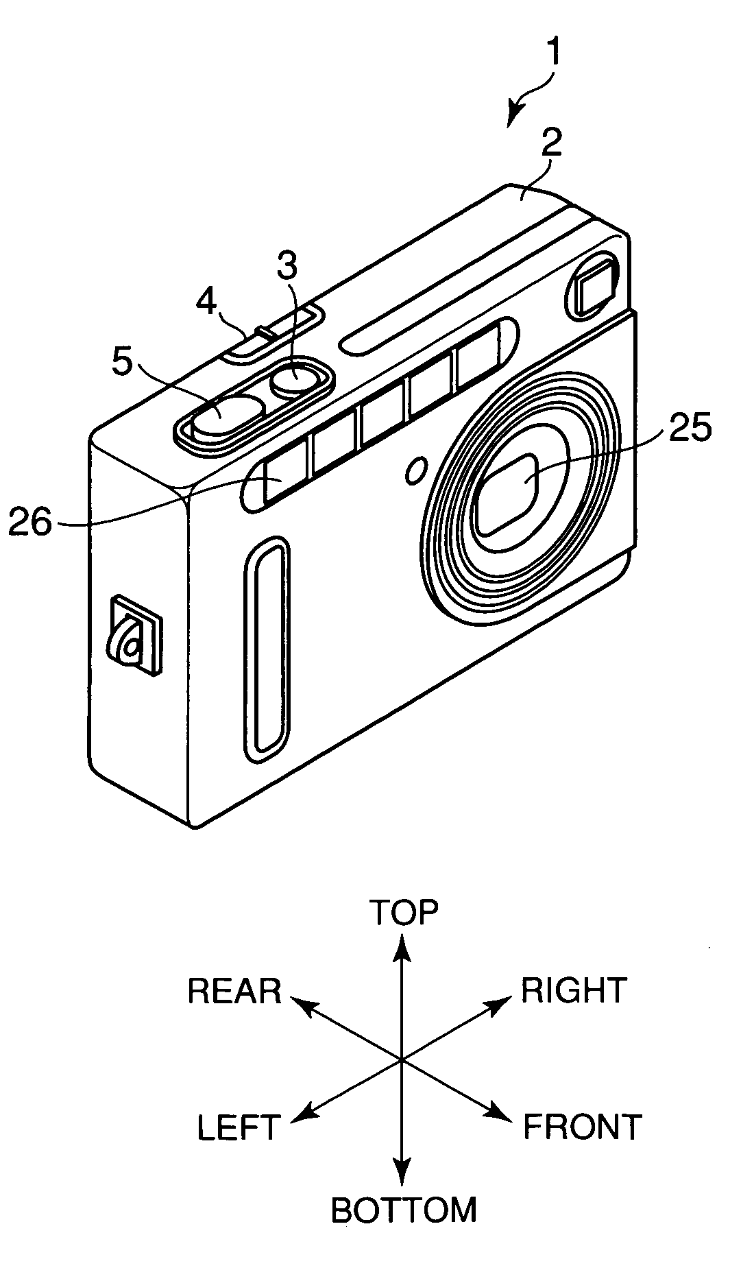
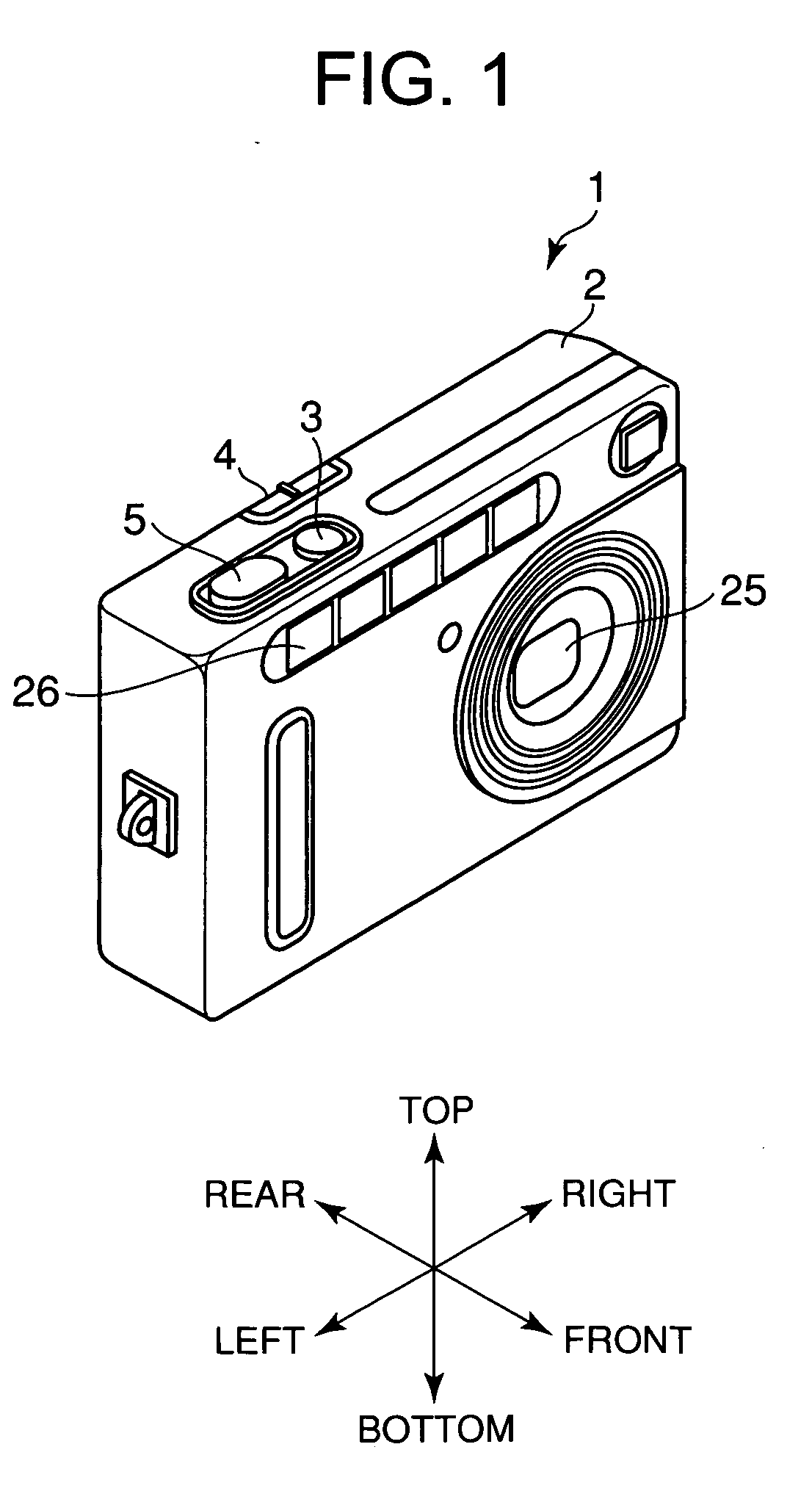
[0187] The flashlight emitting device 26 may be comprised of plural light-emitting members 40 which are disposed in a line along the circumference of the image pick-up lens 31 on the front surface of the housing 2, as shown in FIG. 28.

[0188] Further, modification may be made such that the illumination angle may be switched to a desired direction by selecting an arbitrary light emitting member among those previously arranged so as to face diffe...


PUM


Abstract

An electronic camera comprises a light-emitting unit 38 for emitting light, color components of which can be changed; a color-component measuring unit 51 for obtaining color components involved in any one of light from a light source for illuminating an object and light reflected by the object; an input-image processing unit 52 for determining color components of light to be emitted based on the color components calculated by the color-component measuring unit; and a light-emitting member driving unit 39 for making the light-emitting unit emit light involving the color components determined by the input-image processing unit in response to an instruction of photographing given by a user.

Description

BACKGROUND OF THE INVENTION [0001] 1. Field of the Invention [0002] The present invention relates to an electronic camera, and more particularly, to an electronic camera which is capable of correcting a color temperature characteristic and spectral distribution characteristic of flashlight. [0003] 2. Description of Prior Art [0004] In general, when an object or person is photographed with strobe light, an image photographed under front lighting shows a rather flat image. Therefore, an oblique lighting, side lighting, or combination thereof are used to stress clear-cut feature, shadows and look solid of a face of the person to be photographed, thereby describing minute facial expression. [0005] To realize the oblique lighting or side lighting, an illuminating device and detachable flashlight-emitting device, and the like are used. In the illuminating device and flashlight-emitting device, a light-emitting member of a large guide number (herein after, “GN”) is used, which GN represent...

Claims


Application Information

Patent Timeline
Patent Type & Authority Applications(United States)
IPC IPC(8): G03B15/03
CPCG03B15/05G03B33/00H04N5/2256H04N9/735H04N5/2354H04N9/045H04N5/23293G03B2215/0503H04N23/56H04N23/74H04N23/88
Inventor KITA, KAZUNORI
Owner CASIO COMPUTER CO LTD
Why Eureka
Try Eureka