Structure of joining resin molded bodies

a technology of joining structure and resin molded body, which is applied in the directions of thin material handling, transportation and packaging, layered products, etc., can solve the problem of difficult to achieve reliable and superior joining strength across the entire joining parts in either method, and achieve and reliable and superior joining strength.

Inactive Publication Date: 2006-03-30
DAIKYONISHIKAWA CORP
View PDF3 Cites 17 Cited by
  • Summary
  • Abstract
  • Description
  • Claims
  • Application Information

AI Technical Summary

Benefits of technology

[0014] In the structure of joining the resin molded bodies according to the present invention, the butting area of the protrusions for welding in the tilting portions in the state in which the protrusions are butted is set to be larger than the butting area thereof in the vertical portions in the same state. Therefore, when the vibration welding is carried out while the pressure is applied to the resin molded bodies in the butted state, a welding area in the tilting portions is larger than a welding area in the vertical portions at least in an initial stage of the welding. As a result, the joining strength in the tilting portion, in which it is generally difficult to obtain a reliable and superior joining strength in comparison to the vertical portion, can be enhanced, and the reliable and superior joining strength can be thereby realized across the entire joining parts.
[0015] In the foregoing constitution, the butting area of the protrusions in the vertical portions is preferably set to be larger toward the base of each protrusion. As a result, the welding area in the vertical portions can be increased as the welding advances without necessarily changing the pressurizing force applied to the resin molded bodies though the welding area is relatively small in the initial stage of the welding. Thereby, a required joining strength in the vertical portions can be assured.
[0016] Further, the protrusions in the pressurizing direction more preferably have the substantially rectangular shape in section in the tilting portions so that the welding area is substantially constant regardless of the advancement of the welding. As a result, the reliable joining strength can be obtained. In contrast, the protrusions in the pressurizing direction preferably have the substantially triangular shape in section in the vertical directions so that the welding area can be increased as the welding advances. Therefore, the welding area in the vertical portions can be increased as the welding advances without necessarily changing the pressurizing force though the welding area in the initial stage of the welding is relatively small. As a result, the required joining strength in the vertical portions can be assured. Further, the protrusions in the pressurizing direction preferably have the substantially trapezoidal shape in section between the vertical portions and the tilting portions so that a drastic change of the welding area in the joining region from the tilting portions through the vertical portions can be alleviated. As a result, the reliable and superior joining strength can be realized in the entire joining parts.
[0017] Further, the sectional area of the welding margins of the protrusions in the direction orthogonal to the butting surface in the tilting portions is more preferably set to be equal to or more than the sectional area thereof in the same direction in the vertical portions so that a welding amount in the tilting portions can be equal to or more than a welding amount in the vertical portions in the direction orthogonal to the butting surface. Thereby, the joining strength in the tilting portions, in which it is generally difficult to obtain the reliable and superior joining strength in comparison to the vertical portion, can be enhanced. As a result, the reliable joining strength can be obtained across the entire joining parts in the direction orthogonal to the butting surface.

Problems solved by technology

Yet, it is actually very difficult to attain a reliable and superior joining strength across the entire joining parts in either of the methods.

Method used


Image

  • Structure of joining resin molded bodies
  • Structure of joining resin molded bodies
  • Structure of joining resin molded bodies

Examples


Embodiment Construction

[0037] Hereinafter, a preferred embodiment of the present invention is described referring to the drawings.

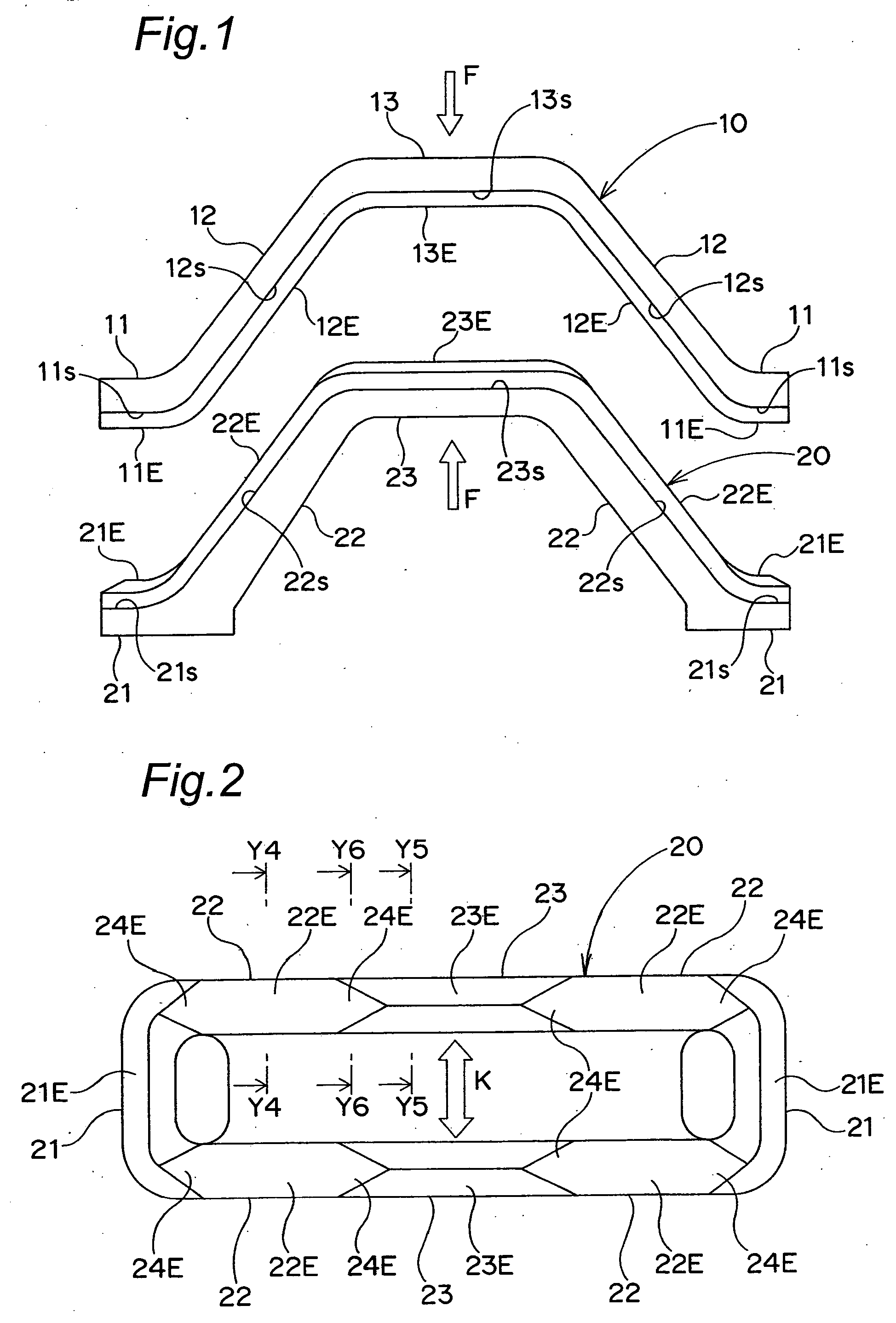
[0038]FIG. 1 is a front view of an upper half body and a lower half body constituting a pair of resin molded bodies according to the present embodiment. FIG. 2 is a plan view of the lower half body.

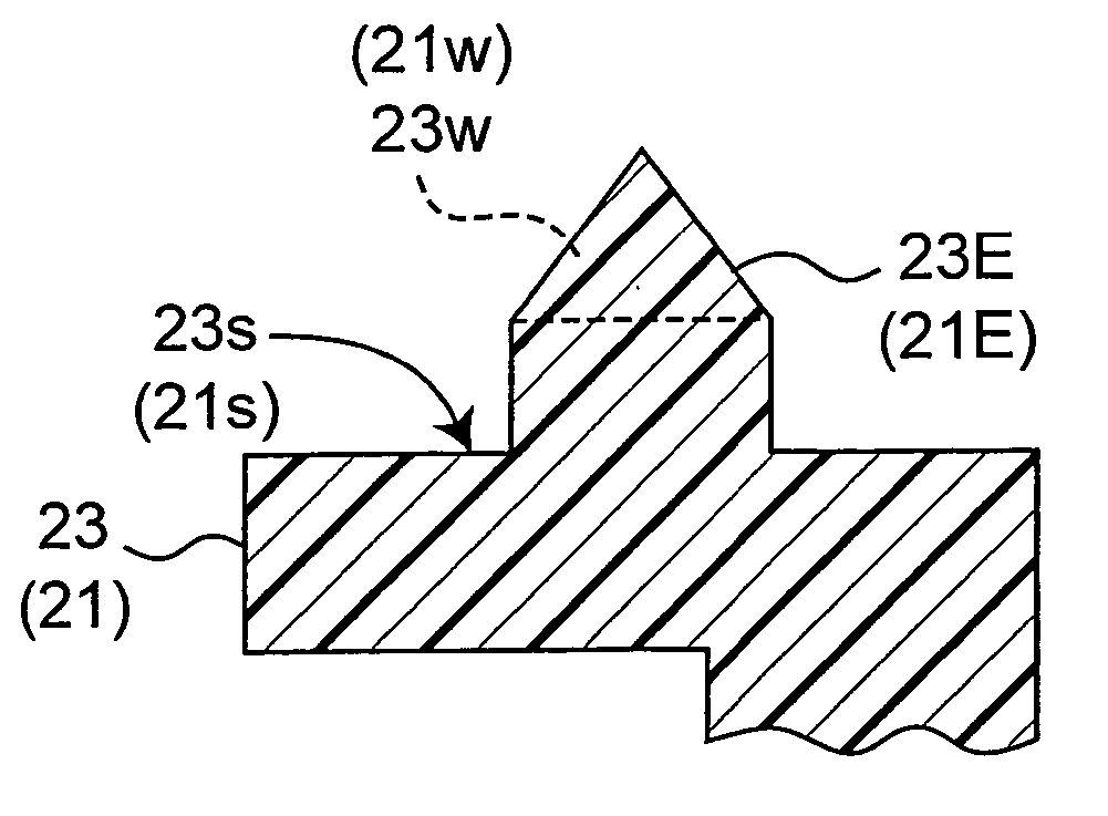
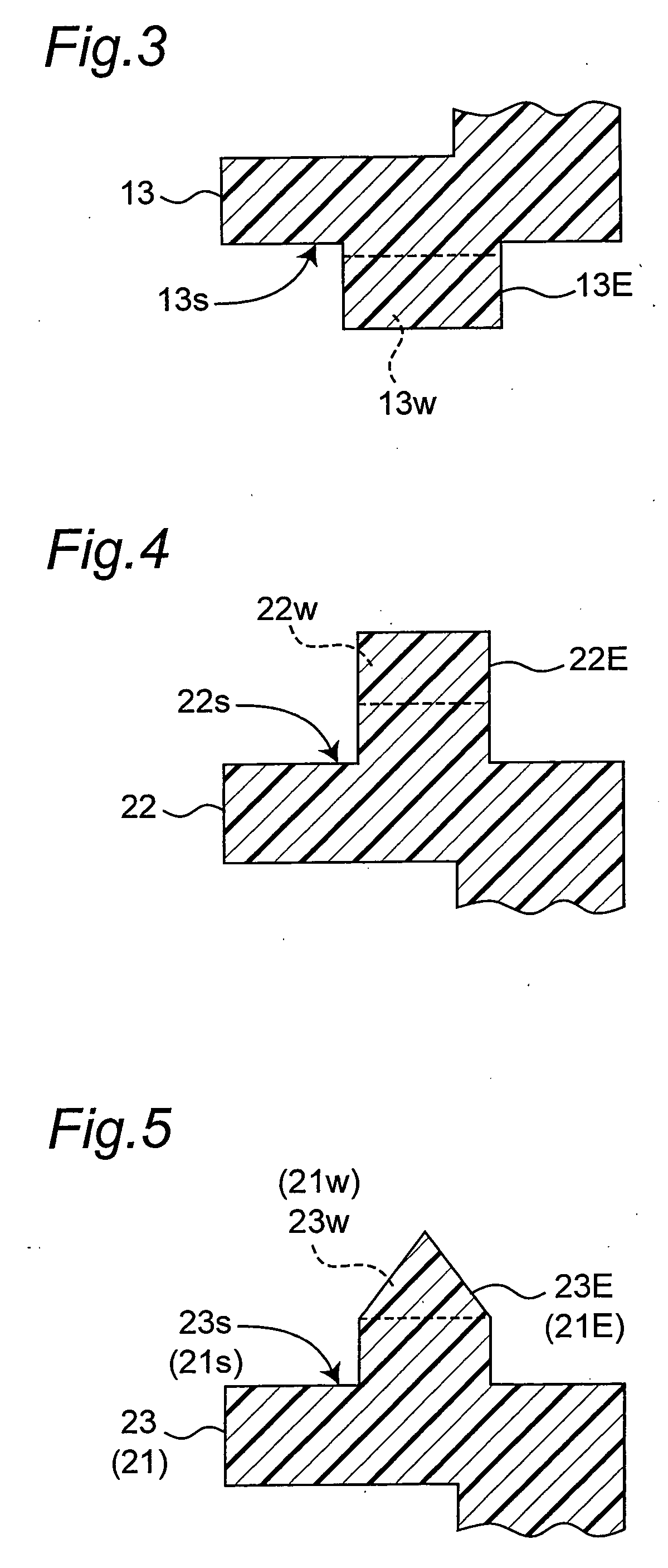
[0039] As shown in FIG. 1, an upper half body 10 and a lower half body 20 are respectively formed into a saddle shape in front view by left and right lower sides 11 and 21, upper sides 13 and 23 substantially in parallel with the lower sides 11 and 21, and slant sides 12 and 22 connecting the upper sides 13 and 23 and the lower sides 11 and 21. When the half bodies 10 and 20 are vertically butted into each other and thereby joined with each other, an integrated resin product comprising a hollow part is formed. In other words, a lower edge of the upper half body 10 and an upper edge of the lower half body 20 respectively constitute joining parts thereof.

[0040] The upper half body 1...


PUM

PropertyMeasurementUnit
heightaaaaaaaaaa
heightaaaaaaaaaa
areaaaaaaaaaaa

Abstract

A reliable and superior joining strength in entire joining parts of resin molded bodies including tilting portions is obtained by devising a shape and a size of each protrusion for welding provided in the joining parts of the resin molded bodies. In a structure of joining resin molded bodies according to the present invention, upper and lower half bodies 10 and 20 are joined with each other by means of a vibration welding method while the upper and lower half bodies 10 and 20 are being pressurized in a state in which joining parts thereof are butted into each other in a substantially entire area of the joining parts. The joining parts of the respective half bodies have vertical portions 11 and 13 and vertical portions 21 and 23 respectively vertical to a pressurizing direction and tilting portions 12 and 22 tilting relative to the pressurizing direction, and protrusions for welding 11E to 13E or 21E to 23E are provided in at least the joining part of one of the half bodies. Further, referring to a butting area of the protrusions in a butted state, the butting area in the vertical portions is set to be narrower than the butting area in the tilting portions.

Description

BACKGROUND OF THE INVENTION [0001] 1. Field of the Invention [0002] The present invention relates to a joining structure of resin molded bodies by means of a vibration welding method while applying a pressure to the pair of resin molded bodies in a state in which joining parts of the pair of resin molded bodies are butted into each other across a substantially entire area of the joining parts. [0003] 2. Description of the Related Art [0004] Conventionally, as a generally known method of joining a pair of resin molded bodies is available a so-called vibration welding method, in which a vibration is applied to the resin molded bodies in a state in which joining parts of the pair of resin molded bodies are butted into each other and pressurized so that the pair of resin molded bodies are joined with each other. [0005] However, it is a publicly known problem in joining the resin molded bodies with each other by means of the vibration welding method that it is quite difficult to obtain a...

Claims


Application Information

Patent Timeline
Patent Type & Authority Applications(United States)
IPC IPC(8): B32B7/00
CPCB29C65/06B29C66/30223Y10T428/195B29C66/545Y10T428/24174B29C66/45B29C66/8322B29C66/71B29C66/1122B29K2077/00
Inventor ENOKIDA, SATOSHIFUJIKAWA, KOICHI
Owner DAIKYONISHIKAWA CORP
Why Eureka
Try Eureka