Composite component

a technology of composite components and components, applied in the field of composite components, can solve problems such as limited effects, and achieve the effects of improving the joining strength between the metal portion and the resin portion

Inactive Publication Date: 2018-11-29
NIHON PLAST CO LTD
View PDF0 Cites 0 Cited by
  • Summary
  • Abstract
  • Description
  • Claims
  • Application Information

AI Technical Summary

Benefits of technology

[0011]According to the composite component according to one aspect of the present invention, it is possible to provide a composite component in which the joining strength between the metal portion and the resin portion is stably improved.
[0012]In the case where the hole portions arranged in rows are connected to each other inside the main body portion with the connecting portion, since the joint portion continuous in a position of the connecting portion can be made continuous over a plurality of hole portions in rows, the joining strength between the metal portion and the resin portion can be further improved.
[0013]In the case where the hole portions in each row and the hole portions in adjacent rows of the hole portions arranged in a plurality of rows are connected to each other inside the main body portion with the connecting portion, since the joint portion continuous in a position of the connecting portion can be made continuous between a plurality of hole portions in rows and hole portions in adjacent rows, the joining strength between the metal portion and the resin portion can be further improved.

Problems solved by technology

However, in the case of the above-described structure, the joining force between the metal portion and the resin portion is due solely to the anchor action caused by the anchor shape of each hole portion with limited effects.

Method used


Image

  • Composite component
  • Composite component
  • Composite component

Examples


first embodiment

[0034]In the following, the configuration of the present invention will be described with reference to the drawings.

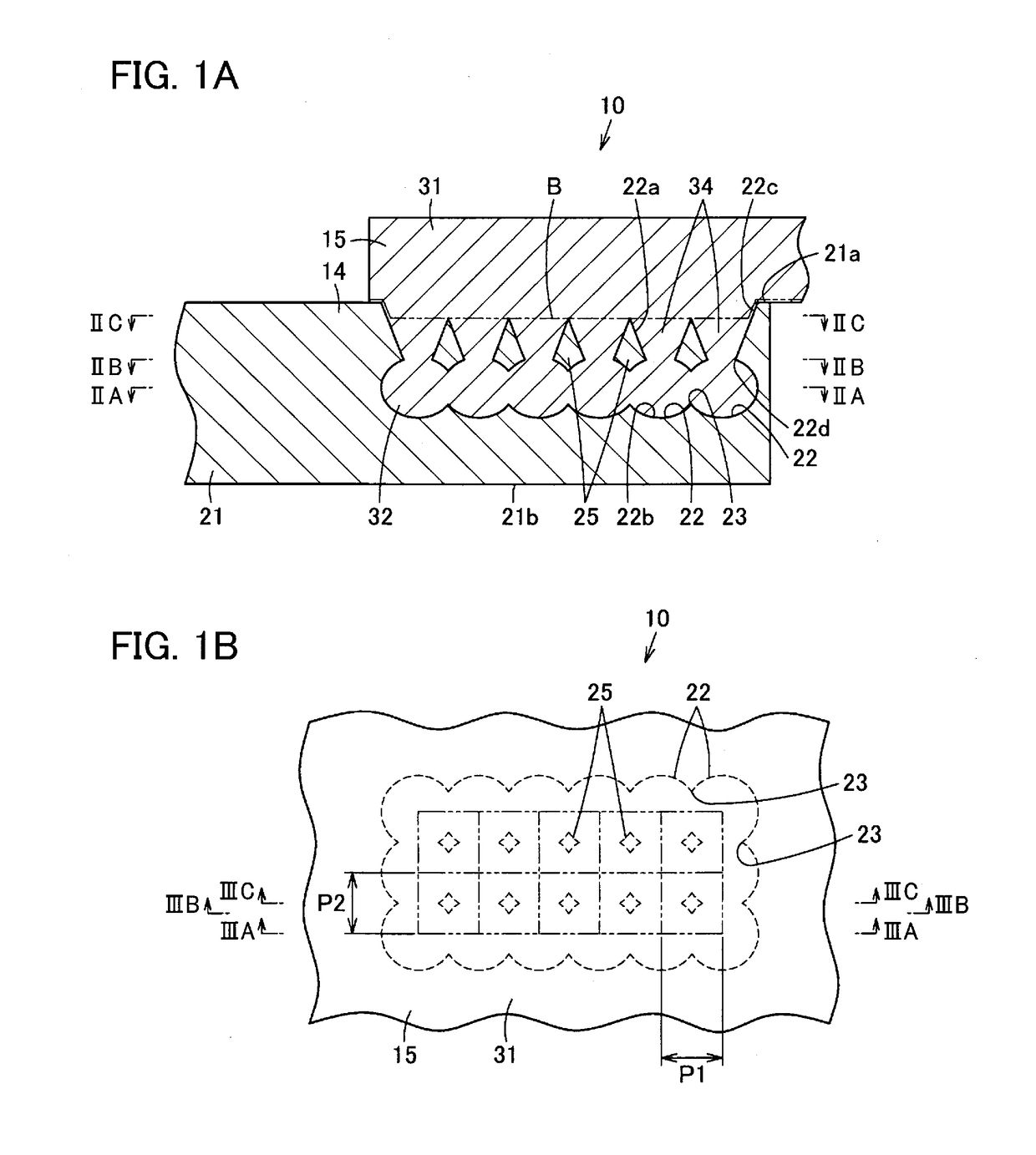
[0035]In FIGS. 1A and 1B, the composite component 10 is for a vehicle such as an automobile. The composite component 10 is suitably used as an optional vehicle structure such as a steering hanger beam (steering member) being a cockpit module component, a cross car beam, a suspension arm, or a strut tower bar.

[0036]Then, the composite component 10 integrally includes a metal portion 14 and a resin component (synthetic resin component) 15.

[0037]The metal portion 14 is formed of a metal such as iron (steel), aluminum, or magnesium, an alloy, or the like. The metal portion 14 can also be referred to as a composite component main body, and is, for example, a main part of the composite component 10. The metal portion 14 includes a main body portion 21. In addition, the metal portion 14 includes a plurality of hole portions 22. Furthermore, the metal portion 14 includes a con...

third embodiment

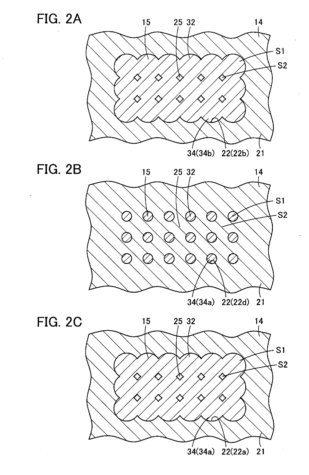
[0073]In addition, as in the third embodiment shown in FIG. 9, for example, a plurality of rows of the hole portion 22 may be formed to be shifted from each other in the direction of this row (one direction), the hole portions 22 may be formed in a zigzag shape (triangular lattice shape (regular triangular lattice shape)), and the plurality of hole portions 22 may be connected in a triangular lattice (regular triangular lattice) with the connecting portion 23 (imaginary line in FIG. 9). In this case, as compared with the above embodiments, the material strength of the metal portion 14 can be further relatively increased.

[0074]That is, as in the above embodiments, changing the arrangement of the rows of the hole portions 22 and the connection part of the hole portions 22 with the connecting portion 23 allows the balance between the material strength of the metal portion 14, the material strength of the resin portion 15, and the fluidity of the molten resin constituting the resin port...


PUM

PropertyMeasurementUnit
weightaaaaaaaaaa
inner diameteraaaaaaaaaa
joining forceaaaaaaaaaa

Abstract

A composite component is a composite component including a metal portion formed of a metal and a resin portion formed of a resin. The metal portion includes: a main body portion, a plurality of hole portions provided along any one of directions separating from each other and directions parallel to each other in the main body portion from outside toward inside, and a connecting portion configured to connect the hole portions to each other inside the main body portion. The resin portion includes: a cover portion covering the main body portion in a position corresponding to at least the hole portions, and a joint portion provided in a protruding manner from the cover portion to be positioned inside the plurality of hole portions, the joint portion being continuous in a position of the connecting portion.

Description

CROSS REFERENCE TO RELATED APPLICATION[0001]This application is based upon and claims the benefit of priority from the prior Japanese Patent Application No. 2017-104938 (filing date: May 26, 2017), and Japanese Patent Application No. 2018-079033 (filing date: Apr. 17, 2018), the entire contents of which are incorporated herein by reference.BACKGROUNDTechnical Field[0002]The present invention relates to a composite component including a metal portion formed of a metal and a resin portion formed of a resin.Related Art[0003]Conventionally, as a metallic structure used for a vehicle such as an automobile, a composite component a part of which is made of a synthetic resin in order to reduce weight is sometimes used. In the case of such a composite component, it is required to firmly join the metal portion and the resin portion.[0004]For example, a configuration in which forming a plurality of hole portions on a front surface of the metal portion, and inserting a part of the resin portion...

Claims


Application Information

Patent Timeline
Patent Type & Authority Applications(United States)
IPC IPC(8): B32B15/08B32B3/30
CPCB32B15/08B32B3/30B62D29/001B32B2250/02B32B2307/718B32B2605/08B29C45/14795B29C2045/14803B29C2045/14868B29L2031/3002B32B3/20B32B3/266B32B15/18B32B15/20B32B2307/542B32B2605/00B62D29/004
Inventor SUZUKI, RYUTA
Owner NIHON PLAST CO LTD
Why Eureka
Try Eureka