

Method for joining metallic members, joint structure and brazing filler metal
a joint structure and filler technology, applied in the direction of manufacturing tools, solvents, transportation and packaging, etc., can solve the problems of serious thermal history and breakage of intermetallic compound layers, and achieve the effect of increasing joint strength and improving joint strength
- Summary
- Abstract
- Description
- Claims
- Application Information
AI Technical Summary
Benefits of technology
Problems solved by technology
Method used
Image

Examples
first embodiment
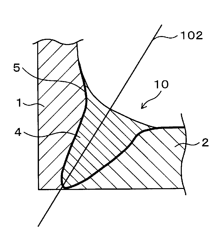
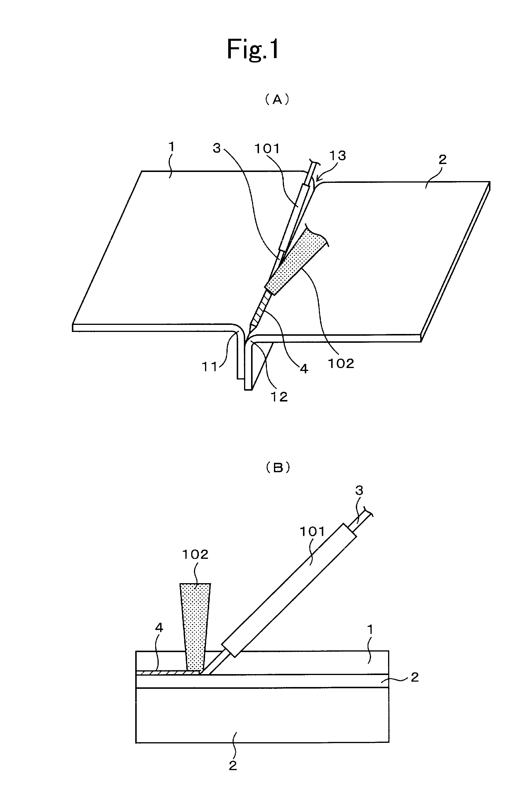
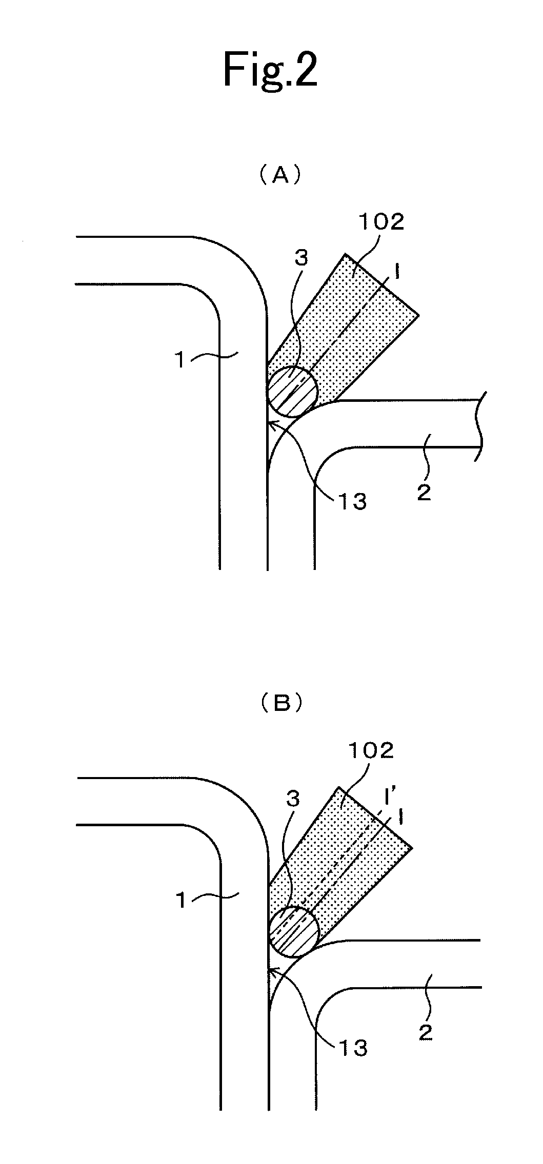
[0069]A first embodiment of the present invention is described below by referring to the Drawings. FIG. 1(A) and FIG. 1(B) show the state that joining is conducted using a method for joining metallic members according to the first embodiment. FIG. 1(A) is a schematic perspective view, and FIG. 1(B) is a schematic front view. FIG. 2(A) and FIG. 2(B) show an example of irradiation state of laser beam to a joined part of metallic members in FIG. 1(A) and FIG. 1(B). FIG. 2(A) is an enlarged front view in the case that the center line of laser beam corresponds to the center line of a groove shape of metallic members, and FIG. 2(B) is an enlarged front view in the case that the center line of laser beam shifts to an Fe-based metallic member side from the centerline of the groove shape of metallic members.
[0070]The method for joining metallic members uses an arrangement for producing, for example, a flare joint. The Fe-based metallic member 1 containing the Fe-based material and an Al-base...
second embodiment
[0092]A second embodiment of the present invention is described below by referring to the drawings. FIGS. 10(A) and 10(B) show a schematic constitution of the state that joining is conducted using a method for joining metallic members according to a second embodiment. FIG. 10(A) is a schematic perspective view, and FIG. 10(B) is a front view.
[0093]The method for joining metallic members uses an arrangement for producing, for example, a flare joint. A Fe-based metallic member 1001 containing a Fe-based material and an Al-based metallic member 1002 containing an Al-based material are used as the metallic members. The Fe-based metallic member 1 and the Al-based metallic member 2 have curved portions 1011 and 1012, respectively. In the arrangement of the Fe-based metallic member 1001 and the Al-based metallic member 1002, the curved portions 1011 and 1012 face each other, and a groove shape 1013 is formed by the curved portions 1011 and 1012. In this case, stepped portion is provided on...
third embodiment
[0120]A third embodiment of the present invention is described below by referring to the drawings. FIG. 19(A) and FIG. 19(B) show schematic constitution of the state that joining is conducted using a method for joining metallic members according to a third embodiment. FIG. 19(A) is a schematic perspective view, and FIG. 19(B) is a view seen from an Al-based metallic member 2002 in FIG. 19(A).
[0121]The method for joining metallic members uses an arrangement for producing, for example, flare joint. A Fe-based metallic member 2001 containing a Fe-based material and an Al-based metallic member 2002 containing an Al-based material are used as the metallic members. The Fe-based metallic member 2001 and the Al-based metallic member 2002 have curved portions 2011 and 2012. In the arrangement of the Fe-based metallic member 2001 and the Al-based metallic member 2002, the curved portions 2011 and 2012 face each other, and a groove shape 2013 is formed by those curved portions 2011 and 2012. I...
PUM
| Property | Measurement | Unit |
|---|---|---|
| melting point | aaaaa | aaaaa |
| height | aaaaa | aaaaa |
| height | aaaaa | aaaaa |
Abstract
Description
Claims
Application Information