Spark plug designed to ensure high strength of electrode joint and production method thereof

Active Publication Date: 2005-08-11
DENSO CORP
View PDF6 Cites 34 Cited by
  • Summary
  • Abstract
  • Description
  • Claims
  • Application Information

AI Technical Summary

Benefits of technology

[0020] According to the second aspect of the invention, there is provided a production method of a spark plug composing the steps of: (a) preparing a hollow cylindrical metal shell which has an inner shoulder formed therein and an end surface with an opening; (b) preparing a cylindrical first electrode and a second electrode, the second electrode being contoured to an inner shape of the metal shell and including an electrode contact and a stopper; (c) disposing the second electrode within the metal shell with the electrode contact abutting the inner shoulder of the metal shell and the stopper exposed to the opening of the end surface of the metal shell; (d) placing a ground electrode on the end surface of the metal shell; and (e) moving the first electrode to press the ground electrode against the end surface of the metal shell until the ground electrode abuts the stopper of the second electrode while supplying an electrical current between the first and second electrodes to resistance-weld the gr

Problems solved by technology

When the ground electrode is joined to the metal shell using typical laser welding techniques, a weld area between them is usually small, which could result in a lack of the strength of the joint between the ground electrode and the metal shell.
Similarly, the weld between the metal shell and the Ni base alloy-made support may lack the mechanical strength because of restriction on a weld area.
Usually, the laser welding results in a considerable rise in temperature of a weld during exposure to laser beams.
After the laser exposure, the weld is cooled rapidly, thus increasing the possibility of solidification cracking thereof, which results in a lack of the strength of the joi

Method used


Image

  • Spark plug designed to ensure high strength of electrode joint and production method thereof
  • Spark plug designed to ensure high strength of electrode joint and production method thereof
  • Spark plug designed to ensure high strength of electrode joint and production method thereof

Examples


fourth embodiment

[0080]FIG. 9 shows a spark plug according to the invention. The spark plug does not have the extension 13. Specifically, the ground electrode 40 is joined directly to the reference surface 12 of the metal shell 10 by the resistance welding. The tip of the center electrode 30 is disposed inside the metal shell 10. In other words, the tip of the center electrode 30 lies inwardly of the reference surface 12 in the longitudinal direction of the metal shell 10. The discharging surface of the ground electrode 40 which faces the center electrode 30 also lies inside the metal shell 10.

first embodiment

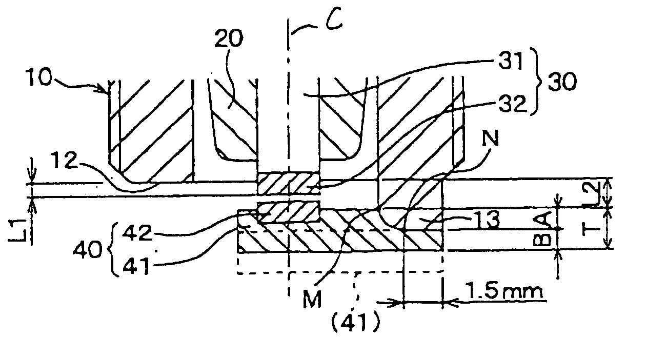
[0081] The distance L1 between the tip end of the chip 32 of the center electrode 30 and the reference surface 12 of the metal shell 10 in the longitudinal direction of the metal shell 10 is 1.3 mm. The distance L2 between the interface M of the ground electrode 40 with the metal shell 10 and the reference surface 12 in the longitudinal direction of the metal shell 10 is 0.8 mm. Other arrangements are identical with those in the first embodiment, and explanation thereof in detail will be omitted here.

[0082] The structure of the spark plug of this embodiment results in a decreased length of the spark plug disposed inside the combustion chamber of the engine, thus decreasing the temperature of the ground electrode 40 during running of the engine.

fifth embodiment

[0083]FIG. 10 shows a spark plug according to the invention.

[0084] The tip of the center electrode 30 is disposed inside the metal shell 10. In other words, the tip of the center electrode 30 lies inwardly of the reference surface 12 in the longitudinal direction of the metal shell 10. The discharging surface of the ground electrode 40 which faces the center electrode 30 lies flush with the reference surface 12 in a lateral direction of the metal shell 10. The distance L1 between the tip end of the chip 32 of the center electrode 30 and the reference surface 12 in the longitudinal direction of the metal shell 10 is 0.5 mm. Other arrangements are identical with those in the first embodiment, and explanation thereof in detail will be omitted here.

[0085]FIG. 11 shows a spark plug according to the sixth embodiment of the invention. The spark plug does not have the extension 13 on the metal shell 10. The ground electrode 40, as clearly shown in the drawing, has a crank-shape and is join...


PUM


Abstract

An improved structure of a spark plug is provided to ensure a high strength of joint between a ground electrode and a metal shell. The ground electrode is resistance-welded to the metal shell so that it is embedded partially in an end surface of the metal shell to create a weld interface extending from the end surface to an inner periphery of the metal shell, thus resulting in an increased size of the weld interface to increase the joint strength. The resistance welding keeps the temperature of a weld between the ground electrode and the metal shell at a lower level during welding as compared with laser welding, thus minimizing solidification cracking in the weld.

Description

CROSS REFERENCE TO RELATED DOCUMENT [0001] The present application claims the benefit of Japanese Patent Application Nos. 2004-30907 and 2004-340406 filed on Feb. 6, 2004 and Nov. 25, 2004, respectively, the contents of which are incorporated herein by reference. BACKGROUND OF THE INVENTION [0002] 1. Technical Field of the Invention [0003] The present invention relates generally to a spark plug which produces a series of sparks to ignite an air-fuel mixture and a production method thereof, and more particularly to such a spark plug designed to ensure a high strength of joint between a ground electrode and a metal shell and a production method thereof. [0004] 2. Background Art [0005] U.S. 2002 / 0063504 A1 (Japanese Patent First Publication No. 2002-222686) discloses a spark plug which has an Ir (iridium) alloy-made ground electrode joined directly to an end surface of a metal shell by laser welding. U.S. Pat. No. 6,307,307 B1 and U.S. Pat. No. 6,373,172 B1 (Japanese Patent First Publi...

Claims


Application Information

Patent Timeline
IPC IPC(8): H01T13/20H01T13/32H01T13/39H01T13/46H01T21/02
CPCH01T21/02H01T13/20
Inventor OKAMOTO, SHIGENORI
Owner DENSO CORP
Why Eureka
Try Eureka