Ceramic member

a technology of ceramic members and connecting parts, applied in the field of ceramic members, can solve the problems that the connection strength between the connection member and the terminal cannot be sufficiently secured, and achieve the effects of high fluidity, poor fluidity, and high wettability to metal

Active Publication Date: 2019-12-24
NGK SPARK PLUG CO LTD
View PDF8 Cites 0 Cited by
  • Summary
  • Abstract
  • Description
  • Claims
  • Application Information

AI Technical Summary

Benefits of technology

[0009]Therefore, an object of the present invention is to provide a ceramic member that can enhance the joining strength between the connection member and the terminal.
[0011]According to the present invention, at least a part of the brazing material solidified portion present between the first metal member serving as a terminal, for example, and the second metal member serving as a connection member, for example, is present in the enlarged portion of the blind hole. Accordingly, this portion exhibits anchor effect, thus enhancing the joining strength between the first metal member and the second metal member.
[0013]In this case, the joining strength between the first metal member and the second metal member can be enhanced over the entire circumference of the enlarged portion.
[0015]In this case, it is preferable to use a brazing material that does not contain a so-called active metal. When the brazing material contains an active metal, a melt of the brazing material has poor fluidity at a temperature higher than or equal to the melting point thereof. Thus, even if a space is present, the melt is relatively difficult to be filled in the space. In contrast to this, a brazing material made of a pure metal or a metal brazing material not containing any active metal has, when in a melt state, relatively high fluidity and higher wettability to metal than to ceramics, and thus, can be filled in the space.

Problems solved by technology

However, with the technology described in Patent Document 1 above, there are cases where the joining strength between the connection member and the terminal cannot be sufficiently secured.

Method used


Image

  • Ceramic member
  • Ceramic member

Examples


Embodiment Construction

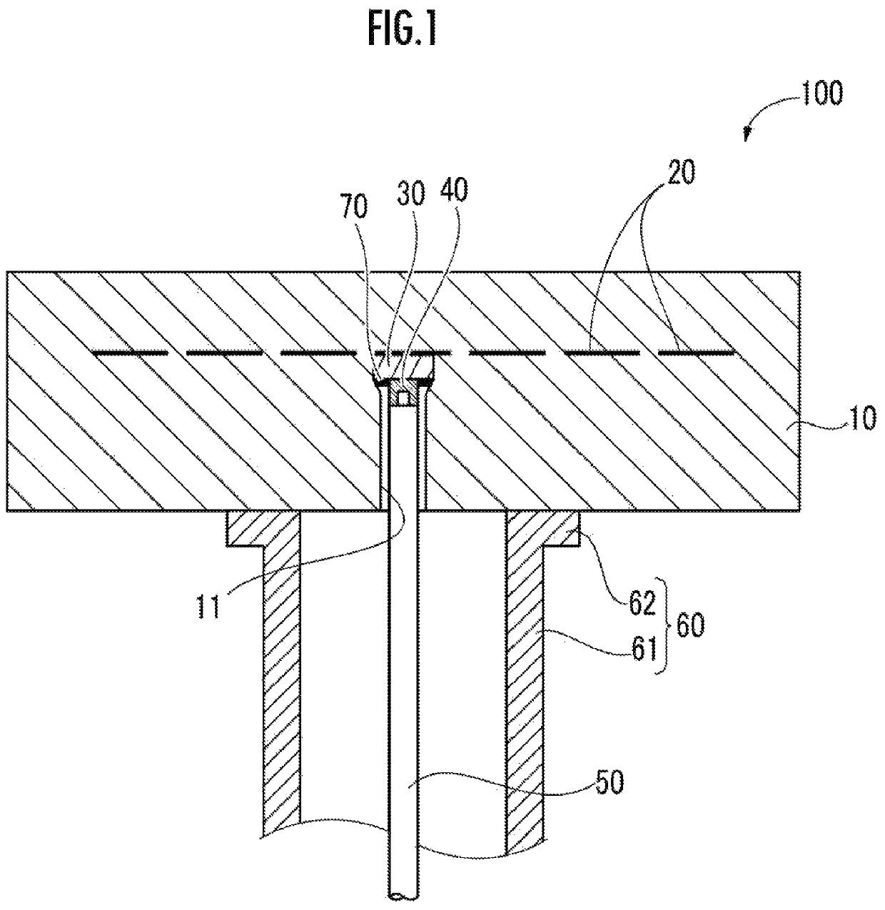
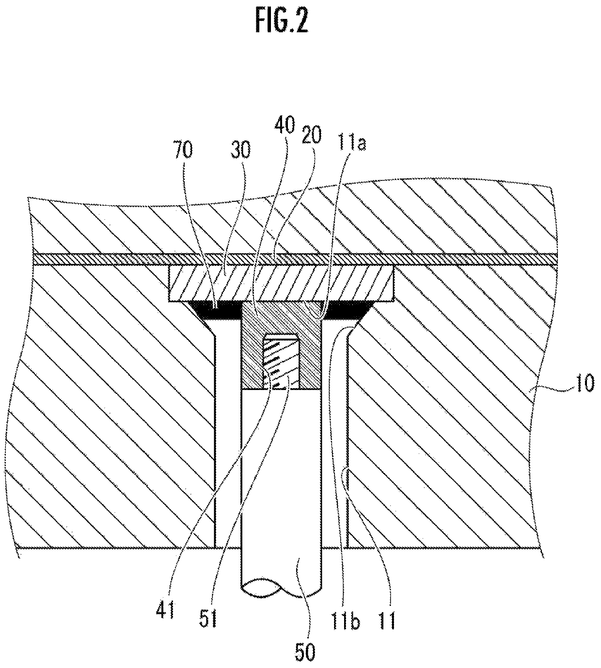
[0019]A ceramic member 100 according to an embodiment of the present invention is described with reference to FIG. 1 and FIG. 2.

[0020]The ceramic member 100 includes a ceramic base body 10, a metal body 20, a terminal (first metal member) 30, a connection member (second metal member) 40, a power feeding rod 50, and a shaft 60.

[0021]The ceramic member 100 here is an electrostatic chuck in which the metal body 20 functions as an electrode, and which suctions a substrate to a surface of the ceramic base body 10 by Coulomb force generated as a result of a voltage being applied from the power feeding rod 50 to this electrode through the terminal 30 and the connection member 40.

[0022]However, the ceramic member 100 may be a heater in which the metal body 20 functions as a heating resistor (heater), and which heats a substrate placed on the surface of the ceramic base body 10, by heat generated as a result of a voltage being applied from the power feeding rod 50 to this heater.

[0023]Furthe...


PUM

PropertyMeasurementUnit
heightaaaaaaaaaa
heightaaaaaaaaaa
diameteraaaaaaaaaa

Abstract

This ceramic member 100 includes: a ceramic base body 10 having a terminal 30 embedded therein; a blind hole 11 formed in the ceramic base body 10 and causing the lower surface of the ceramic base body 10 and the terminal 30 to communicate with each other; and a connection member 40 inserted in the blind hole 11, the connection member 40 connected to the terminal 30 by means of a brazing material solidified portion 70. In the blind hole 11, the space surrounded by the inner peripheral surface of the blind hole 11 has, at least at a bottom face 11a, an enlarged portion 11b that is enlarged toward the upper side at least partially with respect to the circumferential direction, and at least a part of the brazing material solidified portion 70 is present in the enlarged portion 11b.

Description

CROSS REFERENCE TO RELATED APPLICATION[0001]The present application claims priority to Japanese Patent Application No. 2016-150798, which was filed on Jul. 29, 2016, the disclosure of which is herein incorporated by reference in its entirety.BACKGROUND OF THE INVENTIONField of the Invention[0002]The present invention relates to a ceramic member, and in particular, to a ceramic member in which a metal member embedded in a ceramic base body has another metal member brazed to the metal member.Description of Related Art[0003]In a ceramic member, such as an electrostatic chuck or an RF susceptor, used in a semiconductor production device or the like, a voltage is applied through a power feeding rod to a terminal of an electrode, a heater, or the like embedded therein. Thus, in many cases, a metal connection member connected to the power feeding rod is connected to the terminal made of metal.[0004]Inside a blind hole formed in a ceramic base body, the connection member is connected by bra...

Claims


Application Information

Patent Timeline
Patent Type & Authority Patents(United States)
IPC IPC(8): H02N13/00H01L21/67H01L21/683B32B18/00C04B35/111
CPCH01L21/6833H01L21/6831H01L21/67103H02N13/00C04B2235/3217B32B18/00C04B35/111
Inventor TSUCHIDA, ATSUSHI
Owner NGK SPARK PLUG CO LTD
Why Eureka
Try Eureka