Automatic trace determination method and apparatus for automatically determining optimal trace positions on substrate using computation

a trace position and automatic determination technology, applied in the direction of instruments, computer aided design, basic electric elements, etc., can solve the problems of insufficient security, clearance error, and possible clearance error

Inactive Publication Date: 2006-04-06
SHINKO ELECTRIC IND CO LTD
View PDF5 Cites 200 Cited by
  • Summary
  • Abstract
  • Description
  • Claims
  • Application Information

AI Technical Summary

Benefits of technology

[0024] Thus, according to the second embodiment of the present invention, an automatic trace determination apparatus 1 further comprises: moving means 13 that, when clearances between traces passing through bending points on a target line specified arbitrarily and adjacent vias cannot be secured, moves the specified target line in the opposite direction to that in which the minimum traces are drawn out so that at least the clearances can be secured; and replacement means 14 that

Problems solved by technology

However, in the example of FIG. 23, the clearance between the trace W6 and the via V cannot be secured sufficiently and, as a result, a clearance error will occur.
Also, when the pads have an elliptical shape and the pads are not oriented in an identical direction, a clearance error may occur.
On the other hand, for example, as shown in FIG. 26, when the pad B3 is oriented in the direction to be separated from the pad B2, if the wiring pattern is designed unnaturally so that the bending points are aligned in a line (as shown by a dotted line in the figure), the clearance between the

Method used


Image

  • Automatic trace determination method and apparatus for automatically determining optimal trace positions on substrate using computation
  • Automatic trace determination method and apparatus for automatically determining optimal trace positions on substrate using computation
  • Automatic trace determination method and apparatus for automatically determining optimal trace positions on substrate using computation

Examples


first embodiment

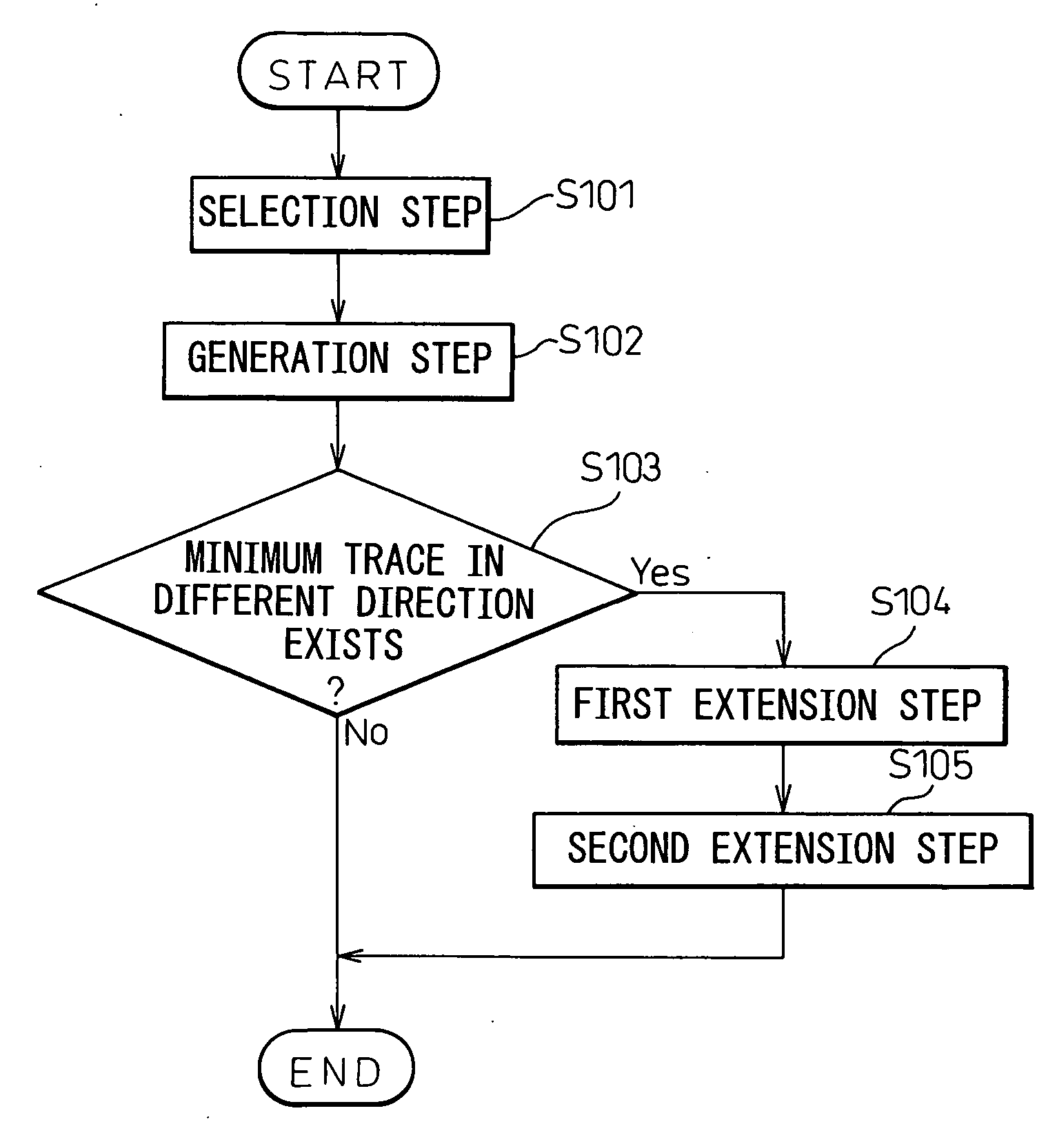
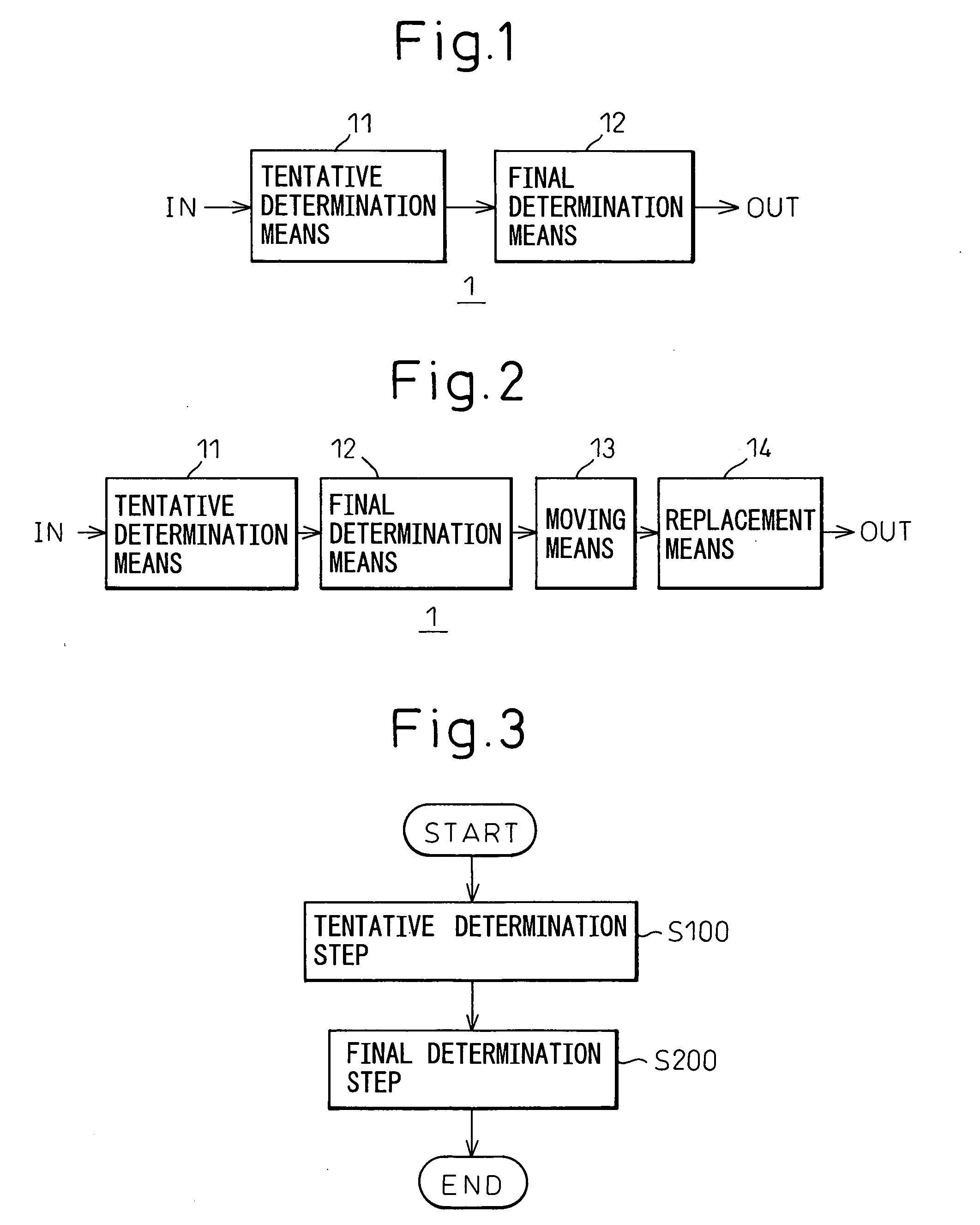
[0053]FIG. 3 is a flow chart showing an operational flow of an automatic trace determination method according to the present invention.

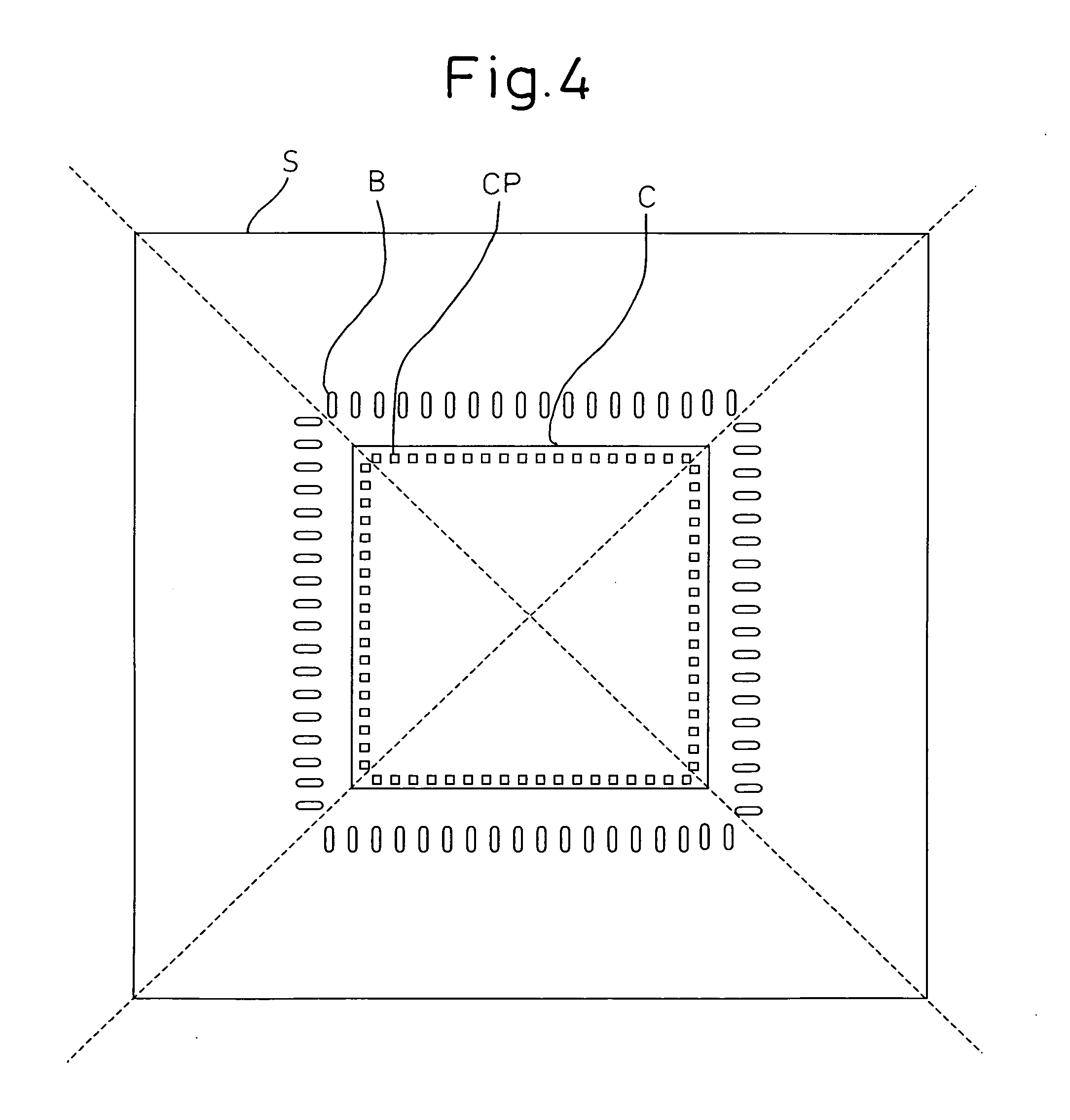
[0054] First, in a tentative determination step S100, a tentative target line with which tentative positions of bending points where traces are bent are aligned is determined tentatively. Next, in a final determination step S200, a final target line is generated by correcting the tentative target line so as to secure at least clearances between adjacent traces and clearances between traces and vias adjacent to the traces. Then, a position of intersection of the final target line and a trace from a pad is determined as a bending point of the trace.

[0055] The tentative determination step S100 and the final determination step S200 in the automatic trace determination method according to the first embodiment of the present invention is performed by a processor such as a computer. In this connection, before performing the tentative determination step S10...

second embodiment

[0107]FIG. 19 is a flow chart showing an operational flow of an automatic trace determination method according to the present invention.

[0108] First, in a manner similar to that in the first embodiment, the tentative determination step S100 and the final determination step S200 are performed. Then, in step S250, it is determined whether there is a user setting to change at least a portion of the final target line generated in the final determination step S200 or not. If there is such user setting, the operation proceeds to a first determination step S301. If there is not such user setting, a result similar to that of the first embodiment described above can be obtained.

[0109] In the first determination step S301, it is determined whether the clearances between the traces passing through the bending points on the specified target line specified arbitrarily and the vias adjacent to the respective traces can be secured or not. If the clearances cannot be secured, the operation proceed...


PUM


Abstract

An automatic trace determination apparatus for automatically determining optimal positions of traces from pads to corresponding vias on a substrate using computation comprises: tentative determination means for tentatively determining a tentative target line with which tentative positions of bending points of traces are aligned; and final determination means for determining a final target line by correcting the tentative target line so that at least clearances between the adjacent traces and between the traces and vias adjacent to the corresponding traces can be secured, wherein the positions of intersection of the determined final target line and the traces from the pads are determined as bending points of the traces.

Description

BACKGROUND OF THE INVENTION [0001] 1. Field of the Invention [0002] The present invention relates to an automatic trace determination method and apparatus for determining optimal trace positions from pads to corresponding vias on a substrate. [0003] 2. Description of the Related Art [0004] In a semiconductor package such as PBGA and EBGA, electrode terminals of a semiconductor chip are electrically connected with pads (for example, bonding pads or flip-chip pads) and the pads are connected with vias (a land), and the vias are also connected with each other by traces (i.e., signal traces). Traces in the semiconductor package at least have to satisfy design rules in that clearances between traces and so on can be secured and there is no unnecessary trace crossing. For example, a designer typically designs a wiring route of a semiconductor package by trial and error on a virtual plane using a CAD system. [0005] For example, Japanese Unexamined Patent Publication No. 2002-08300 disclose...

Claims


Application Information

Patent Timeline
IPC IPC(8): H01L23/52
CPCG06F17/5077G06F2217/40G06F30/394G06F2113/18
Inventor KITAMURA, TAMOTSU
Owner SHINKO ELECTRIC IND CO LTD
Why Eureka
Try Eureka