Multi-point sliding door

a multi-point, sliding door technology, applied in the direction of fastening means, wing fasteners, construction fastening devices, etc., can solve the problems of complicated and expensive, and achieve the effect of simple and inexpensive construction, tolerant of dimensional and configurational variations

Inactive Publication Date: 2006-04-06
FASCO DIE CAST INC A IN CANADA
View PDF13 Cites 58 Cited by
  • Summary
  • Abstract
  • Description
  • Claims
  • Application Information

AI Technical Summary

Benefits of technology

[0004] More specifically this invention is directed to the provision of a sliding door multi-point latch that is simple and inexpensive i

Problems solved by technology

Whereas these multi-point latch structures do increase the strength of the latch and thereby guard against forced entry, they tend to be ver

Method used


Image

  • Multi-point sliding door
  • Multi-point sliding door
  • Multi-point sliding door

Examples


Embodiment Construction

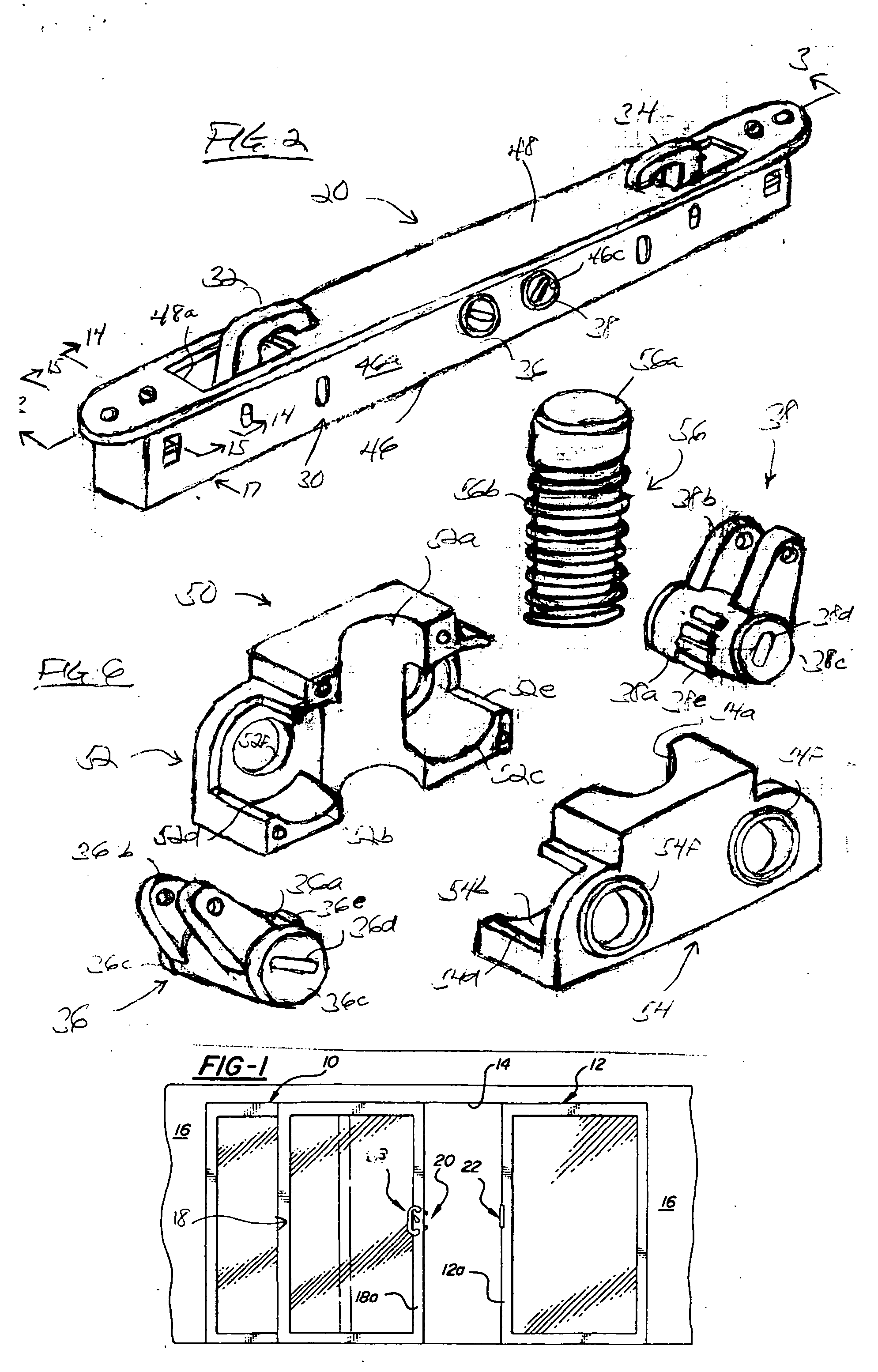
[0030]FIG. 1 illustrates a typical sliding patio door installation in which fixed left and right doors 10 and 12 are positioned at the left and right ends of an opening 14 and a building wall 16 and a sliding door 18 is arranged to move between the open position seen in FIG. 1 to a closed position in which the stile 18a of the sliding door is positioned against a jamb 12a defined by the fixed door 12 so that a latch 20 carried by stile 18a may coact with a keeper plate structure 22 positioned on the jamb 12a to maintain the sliding door in a closed position.

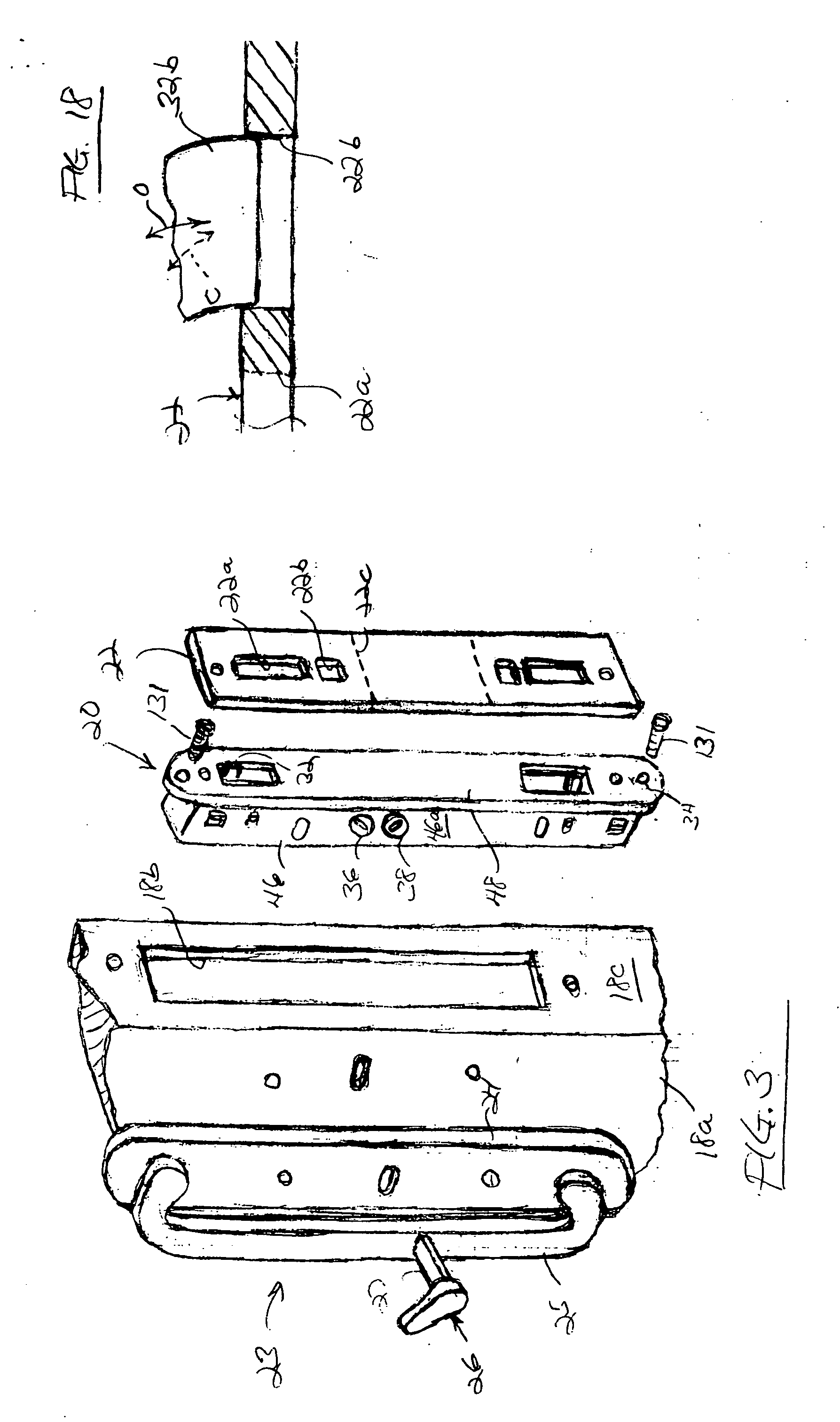
[0031] As seen in FIG. 2, the invention multi-point sliding door latch 20 is adapted to be fitted into a mortise opening 18b in the lock face 18c of the stile 18a of the sliding door and is arranged for coaction with keeper structure 22 positioned on the associated jamb 12a and for coaction with a handle assembly 23 including an escutcheon plate 24 mounted on the inside face of the stile 18a of the sliding door, a handle 25 moun...


PUM


Abstract

A multipoint sliding door latch including a housing, a pair of vertically spaced upper and lower hooks mounted in the housing for movement between a retracted, unlatched position within the housing and an extended, latched position extending out of the housing for engagement with a keeper structure of an associated jamb, upper and lower rotary actuators mounted in the housing in vertically spaced side by side relation between the upper and lower hooks, an upper link mechanism interconnecting the upper actuator and the upper hook and operative in response to rotary movement of the upper actuator to move the upper link from an unlatched to a latched position, and a lower link mechanism interconnecting the lower actuator and the lower hook and operative in response to rotary movement of lower actuator to move the lower hook from an unlatched position to a latched position. The latch further includes a rack positioned between the actuators and defining gear teeth on opposite parallel faces thereof. Each actuator includes pinion gear teeth and the pinion gear teeth of the upper actuator meshingly engage the gear teeth on one face of the rack and the pinion gear teeth on the lower actuator meshingly engage the gear teeth on the opposite face of the rack. The rack comprises a cylindrical member having a series of circumferential ribs defining the gear teeth and the cylindrical rack member is mounted in the housing for rotary movement about its central axis.

Description

BACKGROUND OF THE INVENTION [0001] This invention relates to multi-point door latches and more particularly to a multi-point door latch especially suitable for use with sliding doors. [0002] In a typical sliding patio door installation, the door is maintained in a latched and / or locked condition by a latch mounted in the lock face of the style of the sliding door and having a single hook or other latching element coacting with a keeper structure on the associated door jamb. Whereas these so called single point constructions are satisfactory for most installations, there is increasing need and demand for more security with respect to sliding patio doors to preclude forced entry. In an effort to increase the latch security, so-called multi-point latches have been developed and utilized in which more than one latching element engages the keeper structure of the jamb to provide a more secure latching arrangement and provide more security against forced entry. Whereas these multi-point l...

Claims


Application Information

Patent Timeline
IPC IPC(8): E05C19/10
CPCE05B63/12E05B65/0811E05C9/046E05C9/1875E05C9/10Y10T292/0828
Inventor DENYS, ANDRE
Owner FASCO DIE CAST INC A IN CANADA
Why Eureka
Try Eureka