Vehicle seat

a seat and vehicle technology, applied in the field of seats for vehicles, can solve the problems of limiting the sliding distance of the seat in the fore-aft direction, unfavorable occupant movement within the vehicle, and inability to make it sufficiently easy for occupants to move within the vehicl

a seat and vehicle technology, applied in the field of seats for vehicles, can solve the problems of limiting the sliding distance of the seat in the fore-aft direction, unfavorable occupant movement within the vehicle, and inability to make it sufficiently easy for occupants to move within the vehicl

US20060071527A1Inactive Publication Date: 2006-04-06JOHNSON CONTROLS AUTOMOTIVE SYSTEMS CORP

Image

  • Vehicle seat
  • Vehicle seat
  • Vehicle seat

Examples


Embodiment Construction

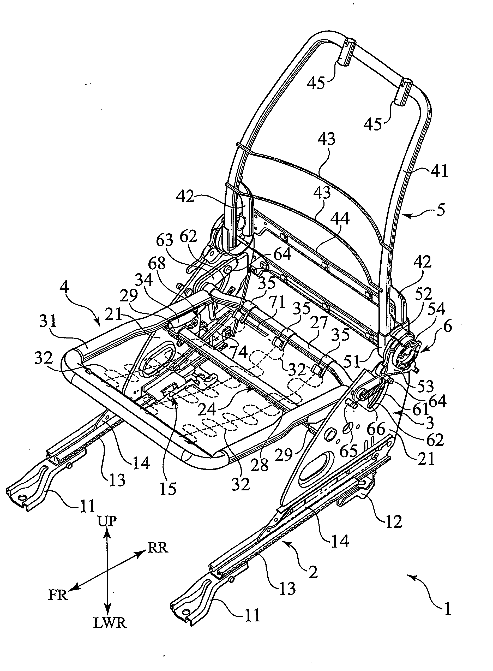
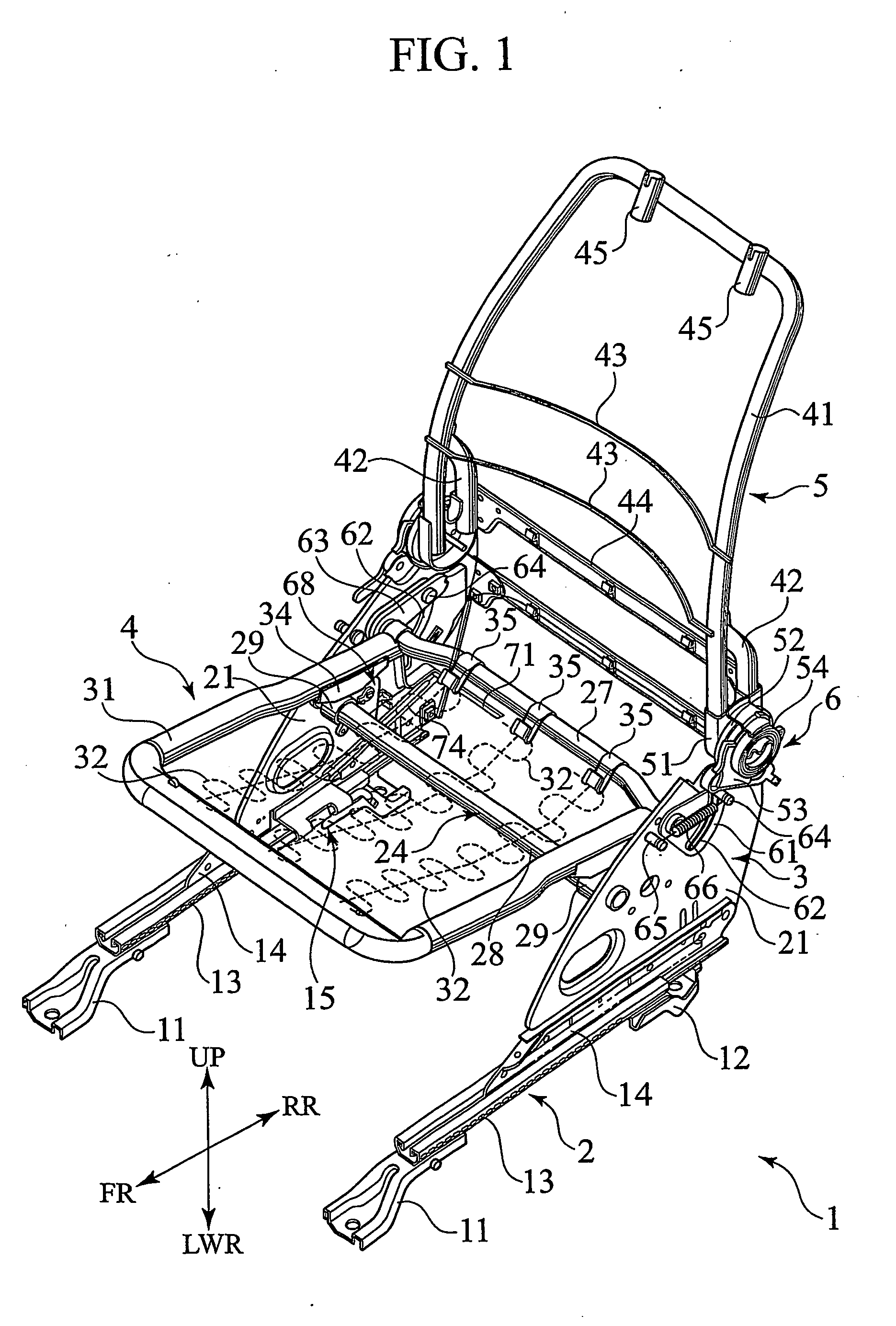
[0015] A seat for a vehicle, in which a shift of a lever alone enables tipping-up of a seat cushion, reclining of a seatback, and sliding the seat is provided. The seat can be slid in a relatively greater and larger distance because the seat cushion moves accompanying with tipping-up thereof. Such a movement, as well as reclining the seatback, improves the ability of an occupant to move within the vehicle.

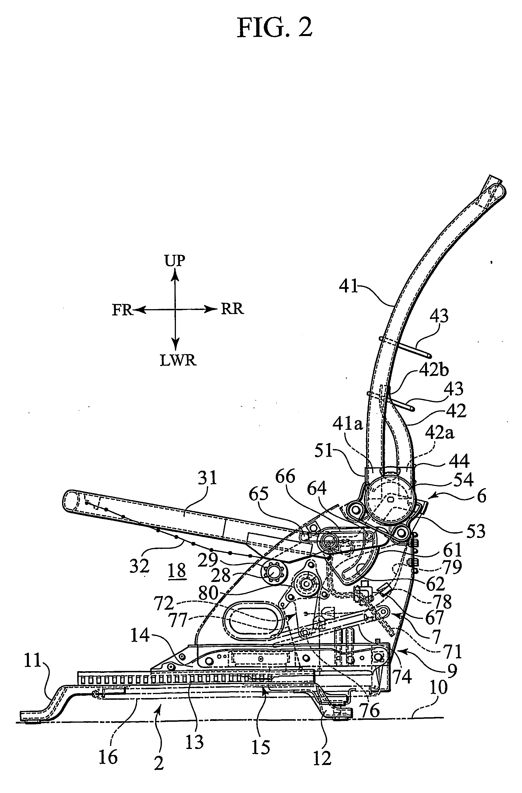
[0016] A seat apparatus 1 according to an embodiment of the present invention will be described hereinafter with reference to FIGS. 1 through 5. With reference to FIGS. 1 through 4, FR denotes “forward”, RR denotes “rearward”, UP denotes “upward” and LWR denotes “downward”. These directions are defined for convenience of an explanation and any embodiments opposed to such a definition are intended to be within the scope of the present invention.

[0017] The seat apparatus 1 comprises a basic framework of a seat for a vehicle and, as shown in FIGS. 1 and 2, is generally provided with...


PUM


Abstract

A seat for a vehicle is provided with a sliding device including a slide-lock mechanism, the sliding device sliding a seat body in a case of releasing the slide-lock mechanism, a seatback including a reclining device, the seatback being tilted forward in a case of releasing the reclining device, a seat cushion including a tip-up device, the seat cushion being tipped up in a case of operating the tip-up device and a walk-in mechanism including a lever, the walk-in mechanism configured to release the slide-lock mechanism, release the reclining device and operate the tip-up device in proportion to a shifting length of the lever. The tip-up device is operated in a case where the lever is shifted in an intermediate position and the slide-lock mechanism and the reclining device are released in a case where the lever is shifted in an end position.

Description

CROSS-REFERENCE TO RELATED PATENT APPLICATIONS [0001] The present Application claims the benefit of priority to the following international Applications: PCT Patent Application No. PCT / JP2003 / 003726 titled “Seat for Vehicle” filed on Mar. 26, 2003 which published under PCT Article 21(2) on Oct. 9, 2003 as WO 03 / 082624 A1 in the Japanese language and Japanese Patent Application No. 2002-94619 filed on Mar. 29, 2002 (which are hereby incorporated herein by reference in their entirety).FIELD [0002] The present invention relates to a seat for a vehicle such as an automobile, a ship, an airplane or a railroad coach, and, more specifically, to a seat for a vehicle making it easy for an occupant to move within the vehicle. BACKGROUND [0003] A vehicle, such as an automobile, is generally provided with relatively large seats in comparison to the spatial dimensions of the interior thereof so as to provide laid-back seating for occupants. Therefore it is often uneasy for the occupants to move ...

Claims


Application Information

Patent Timeline
06 Apr 2006
Publication
US20060071527A1
IPC
B60N2/20; A47C1/024; B60N2/12
CPC
B60N2/08; B60N2/12; B60N2/68; B60N2/22; B60N2/305; B60N2/20
Inventors
PARK, GIL SAM