Medical device with articulating shaft

Active Publication Date: 2006-04-06
BANNERMAN BRETT
View PDF11 Cites 48 Cited by
  • Summary
  • Abstract
  • Description
  • Claims
  • Application Information

AI Technical Summary

Benefits of technology

[0016] An articulator is coupled to the first slat assembly and the second slat assembly such that operation of the articulator causes one of the first and second slat assemblies to push and the other of the first and second slat assemblies to pull simultaneously. In a preferred embodiment, movement of the articulator in one direction causes the bendable portion to bend in an opposite direction away from the direction of movement of the articulator. Alte

Problems solved by technology

Articulating shafts in the prior art include complex mechanisms that are expensive to manufacture and difficult to assemble.
These complexities have derived, at least in part, from the need to provide tension in order to cause the shaft to bend.
Since the pathway to a particular desired location in a human body is often circuitous in more intricate surgical procedures, bending a shaft in only one direction can be very limiting.
Of course, having to manipulate a knob to rotate a shaft and then having to pull a tension mechanism to bend a shaft increases the complexity of a surgical procedure.
Articulating sha

Method used


Image

  • Medical device with articulating shaft
  • Medical device with articulating shaft
  • Medical device with articulating shaft

Examples


Embodiment Construction

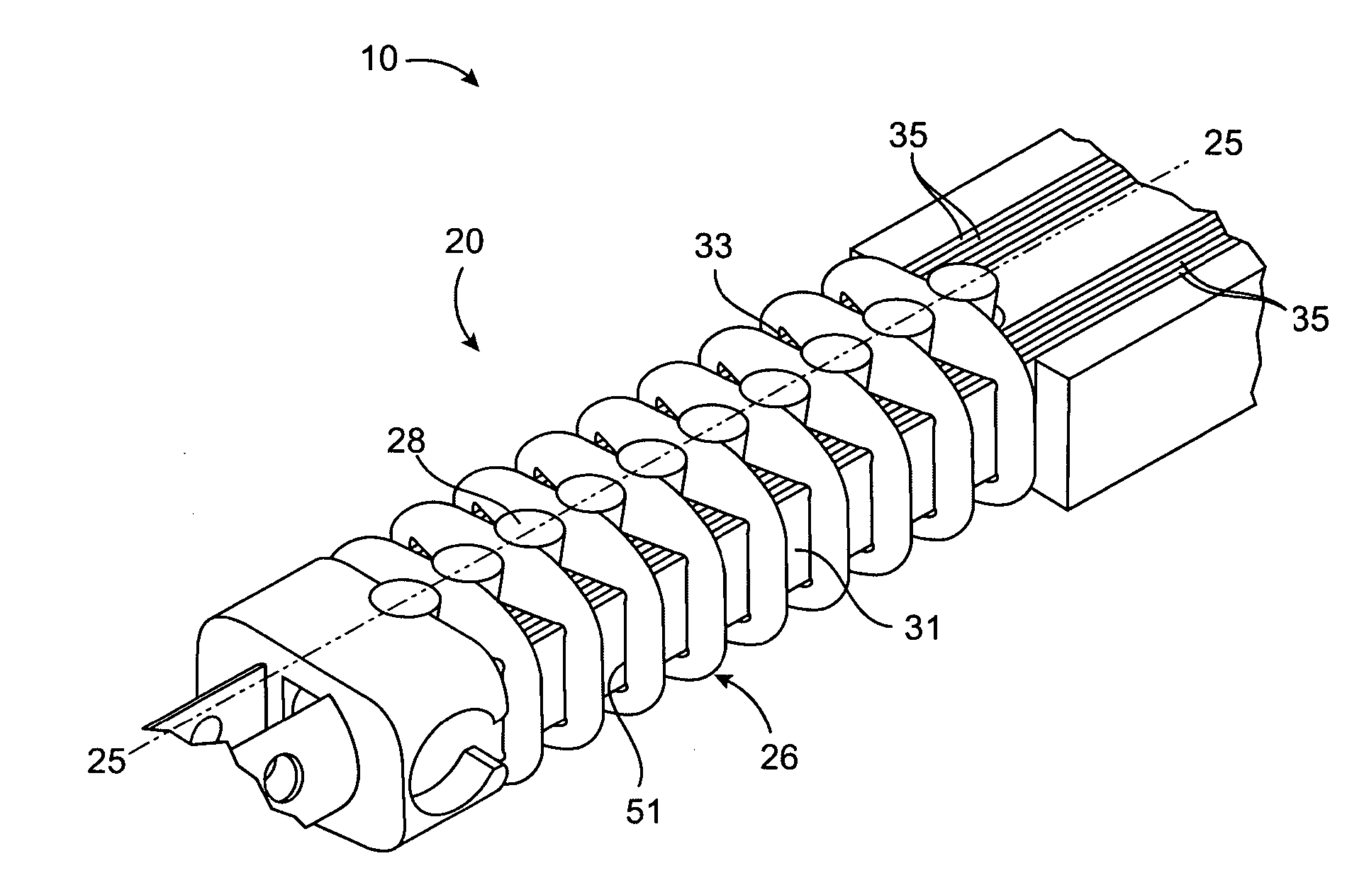
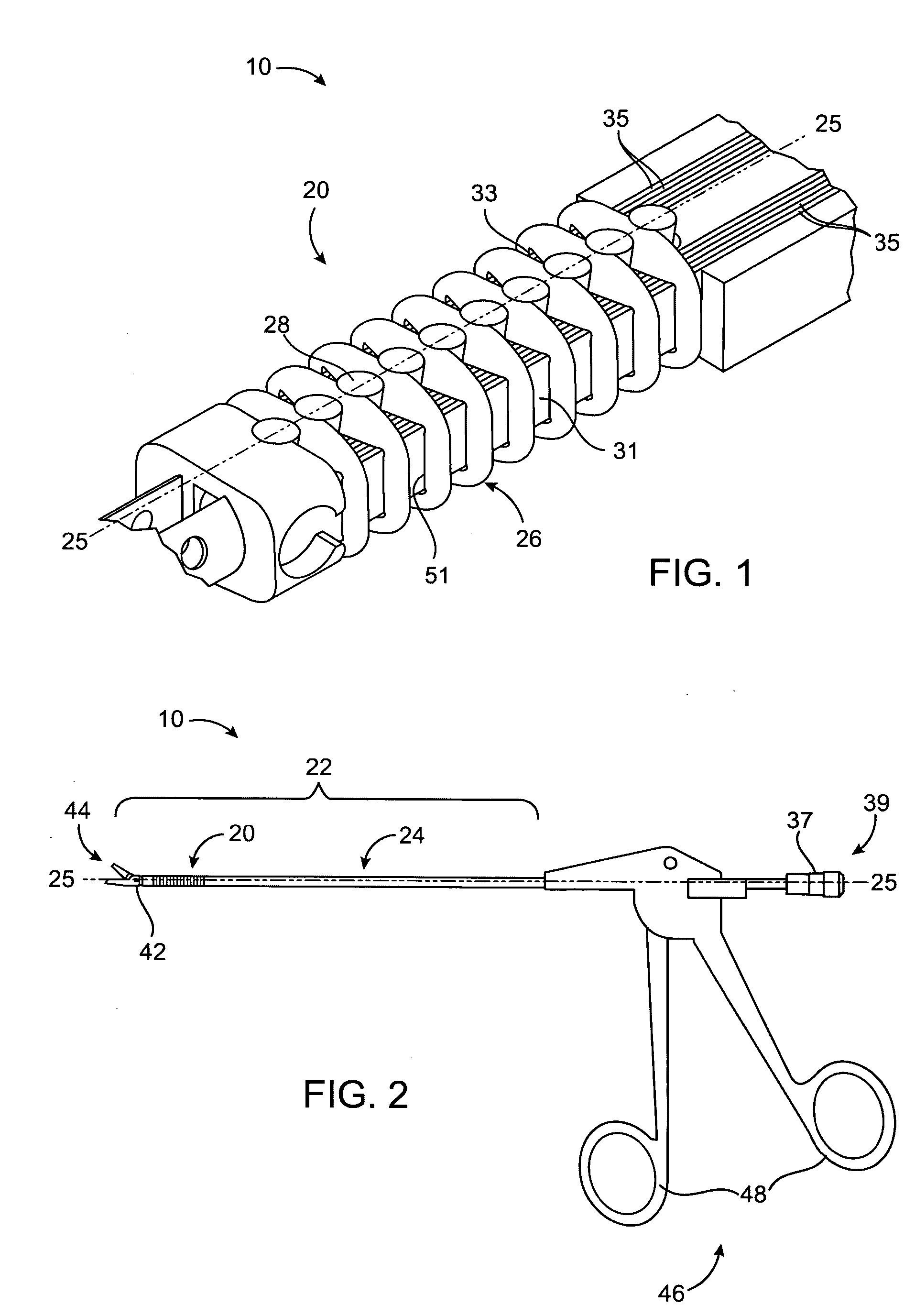
[0045] A first preferred embodiment of a medical device is illustrated in FIGS. 1 and 2 and designated generally by the reference numeral 10. The medical device, or instrument, 10 is particularly configured for intricate surgical procedures where a direct, straight path to a desired destination is unavailable. In particular, endoscopic surgeries typically require circumnavigation around particular areas within the human body in order to reach a desired location for treatment.

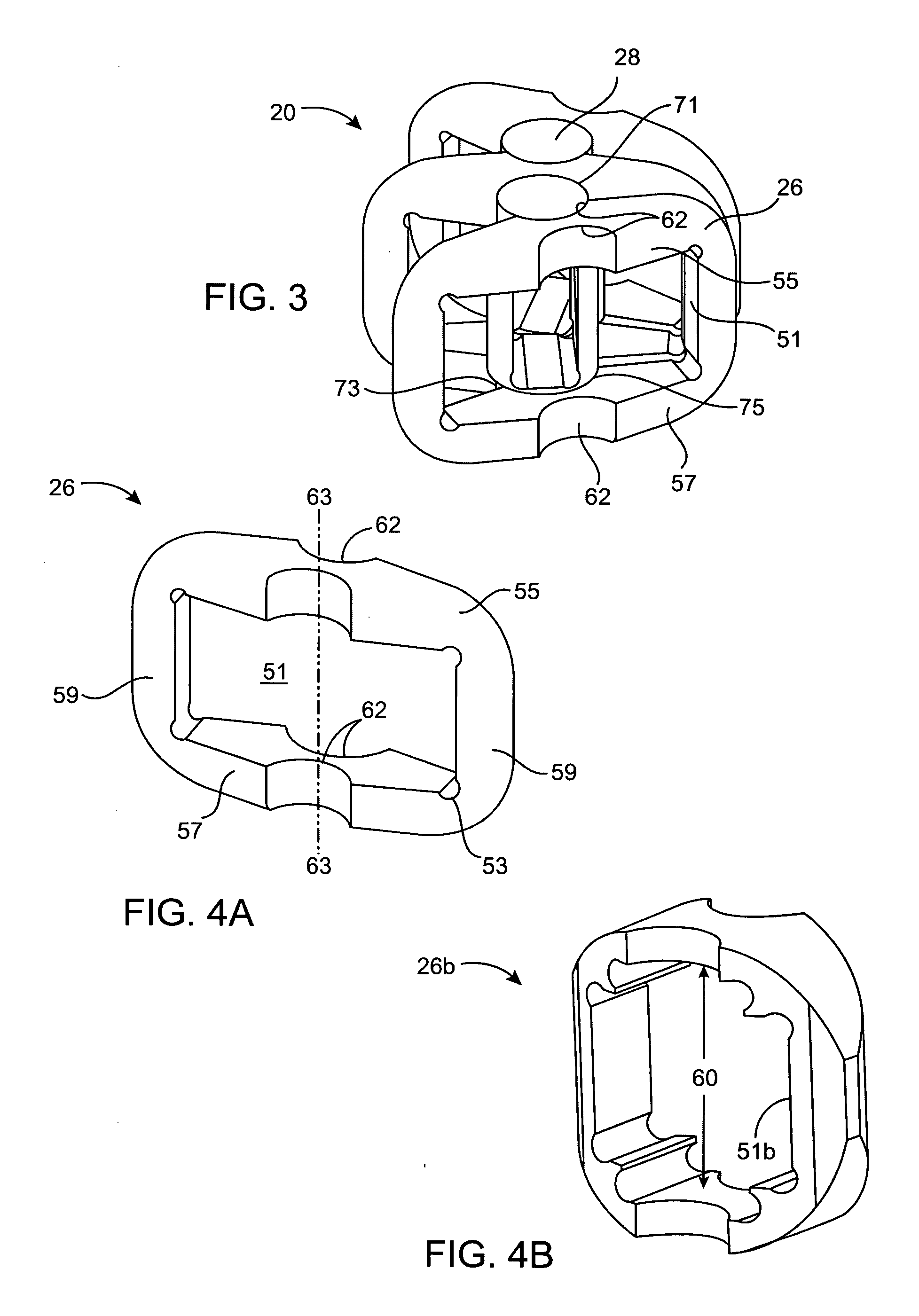
[0046] The device 10 includes an articulating shaft, or bendable portion, 20 of particular interest to the invention. The articulating shaft 20 is formed as a distal portion of an overall shaft 22 that also includes a proximal rigid shaft portion 24. The overall shaft 22 defines a longitudinal axis 25. In the first preferred embodiment, the articulating shaft 20 comprises a plurality of independent pivot members 26 and pins 28 disposed in an alternating configuration. Thus, each pin 28 abuts an adjacent, but se...


PUM


Abstract

A medical device includes an articulating shaft with a pair of slat assemblies. By moving an articulator, the slat assemblies are configured to concurrently push while the other pulls in order to bend the articulating shaft. The articulating shaft includes a series of alternating pins and pivot members. Each pin defines an aperture that collectively forms a passageway for receiving an actuator or a tube. The pair of slat assemblies extend generally parallel to each other on opposite sides of the pins. A method for articulating a shaft of a medical device is also provided.

Description

RELATED APPLICATIONS [0001] This application relates to, claims priority from, and incorporates herein by reference, as if fully set forth, the following: [0002] 1) U.S. Provisional Patent Application Ser. No. 60 / 606,245 filed on Aug. 31, 2004 and entitled “METHOD OF CREATING A FLEXIBLE SHAFT”; [0003] 2) U.S. Provisional Patent Application Ser. No. 60 / 646,966 filed on Jan. 24, 2005 and entitled “METHOD OF CREATING A FLEXIBLE SHAFT”; and [0004] 3) U.S. Provisional Patent Application Ser. No. 60 / 676,456 filed on Apr. 28, 2005 and entitled “METHOD OF CREATING A FLEXIBLE SHAFT, PART C”.BACKGROUND OF THE INVENTION [0005] 1. Field of the Invention [0006] The invention relates generally to surgical devices and methods, and more particularly to shafts. [0007] 2. Description of Prior Art and Related Information [0008] In various types of surgical procedures, particularly in endoscopy, a need exists for articulating, or bendable shafts. Such shafts are preferable, and often times necessary, f...

Claims


Application Information

Patent Timeline
IPC IPC(8): A61B17/00
CPCA61B17/29A61B17/320016A61B17/3201A61B2017/00314A61B2017/00327A61B2017/2902A61B2017/2905A61B2017/2908
Inventor PADGET, MARTINSKINLO, DAVIDWEISEL, THOMASCHU, LONGO
Owner BANNERMAN BRETT
Why Eureka
Try Eureka