Rotatable sheath, assembly and method of manufacture of same

Inactive Publication Date: 2006-04-06
BOSTON SCI SCIMED INC
View PDF9 Cites 52 Cited by
  • Summary
  • Abstract
  • Description
  • Claims
  • Application Information

AI Technical Summary

Benefits of technology

[0024] In some embodiments the sheath may be configured to encourage a portion of the stent to have different deployment characteristics than the remainder of the stent. For example, in at least one embodiment a portion of the sheath may be provided with a region that is selectively thinned, removed, and/or other wise weakened. Such a “weakened” region on a selected portion of the sheath will allow a portion of the expanding balloon thereunder to push outward to a greater extent than those portion restricted by the rest of the sheath. As a result

Problems solved by technology

Treatment at bifurcation sites has been difficult.
Although efforts have been made to use a stent at bifurcations, these sites have previously been problematic to treat.
However, problems are still encountered in orienting such stents relative to the branch openings at the bifurcation of the primary and secondary passages.
Moreover, such bifurcated asse

Method used


Image

  • Rotatable sheath, assembly and method of manufacture of same
  • Rotatable sheath, assembly and method of manufacture of same
  • Rotatable sheath, assembly and method of manufacture of same

Examples


Embodiment Construction

[0046] While this invention may be embodied in many different forms, there are described in detail herein specific preferred embodiments of the invention. This description is an exemplification of the principles of the invention and is not intended to limit the invention to the particular embodiments illustrated.

[0047] For the purposes of this disclosure, like reference numerals in the figures shall refer to like features unless otherwise indicated.

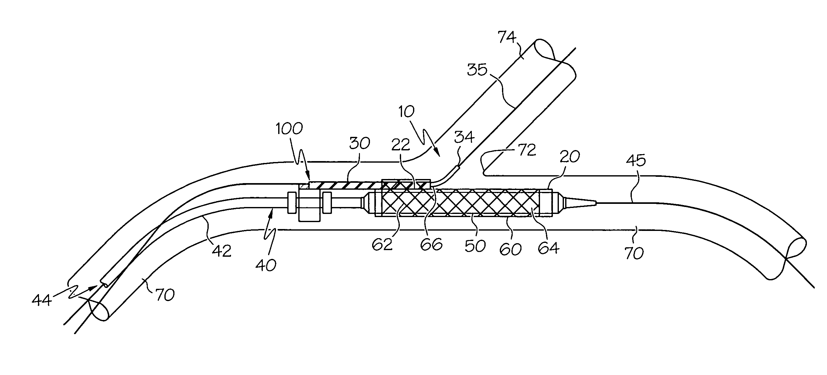
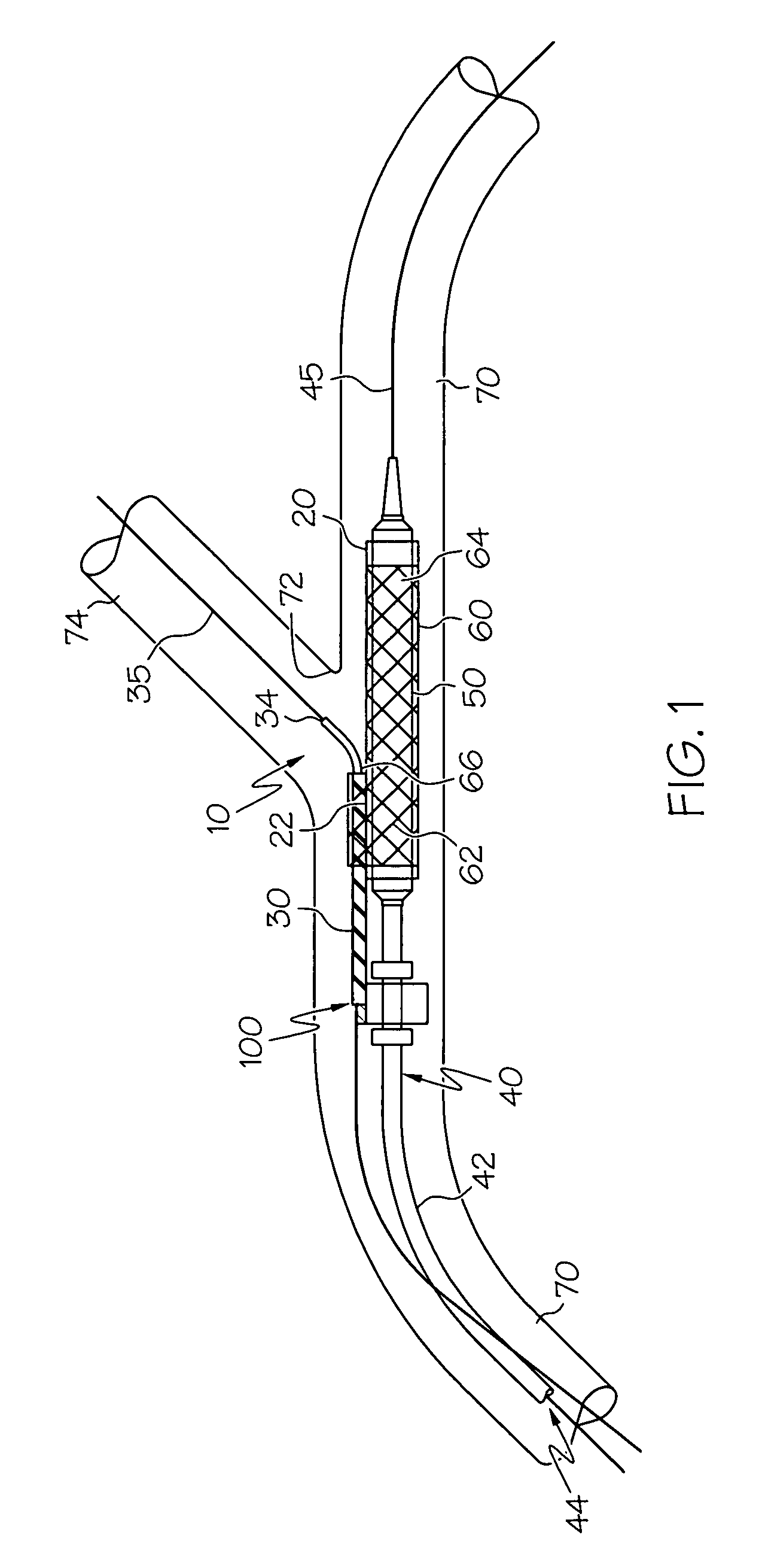
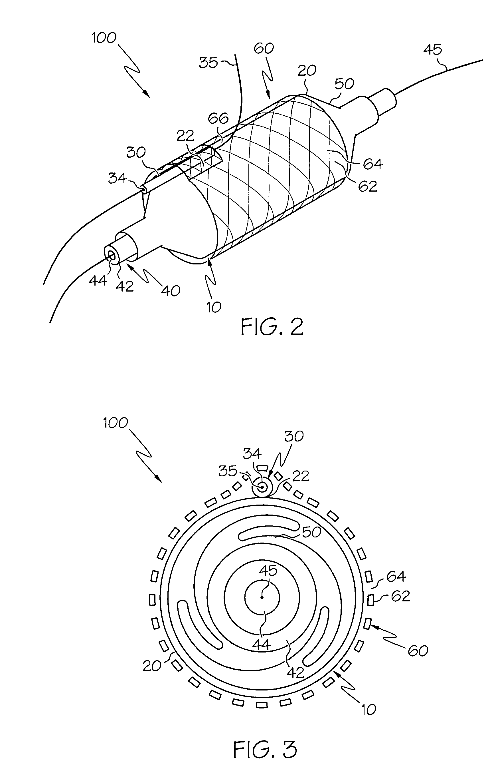
[0048] Referring now to the drawings which are for the purposes of illustrating embodiments of the invention only and not for purposes of limiting same, FIG. 1 illustrates a stent delivery system 100 having a rotatable sheath assembly 10 comprised of tubular sleeve or sheath 20 and a positioning or secondary guidewire housing 30. The assembly 10 is disposed about at least a portion of a balloon 50 of a catheter 40. The rotatable assembly 10 provides the system 100 with a rotating region that allows a stent 60 to be rotationally aligned ...


PUM

PropertyMeasurementUnit
Thicknessaaaaaaaaaa
Diameteraaaaaaaaaa

Abstract

A medical device comprises a catheter having a catheter shaft and a medical balloon positioned thereon, as well as a rotatable assembly disposed about the balloon. The balloon has a pre-expansion state and an expanded state. The rotatable assembly comprises a sheath, wherein the sheath is disposed about the balloon in both the pre-expansion state and in the expanded state. The sheath is rotatable about the balloon in the pre-expansion state. The sheath comprises an inner layer and an outer layer, the inner layer is in rotatable contact with the balloon and the outer layer is disposed about the inner layer. The inner layer is at least partially constructed of at least one material having a durometer value greater than that of the outer layer.

Description

CROSS-REFERENCE TO RELATED APPLICATIONS [0001] Not Applicable STATEMENT REGARDING FEDERALLY SPONSORED RESEARCH [0002] Not Applicable BACKGROUND OF THE INVENTION [0003] Catheter systems such as angioplasty catheters, and stent delivery systems, as well as the stents associated therewith, are widely used in the treatment of stenoses, aneurysms, lesions, and other abnormalities within blood vessels and other body lumens. Intravascular stents are used in coronary, renal, and carotid arteries, for example, to maintain an open passage through the artery. In patients whose coronary heart disease consists of focal lesions, stents have proven effective. For example, where only a single coronary artery is clogged or where there are short blockages in more than a single artery, stents have been used with a great amount of success. An intravascular stent may be positioned in a clogged artery by a catheter and is often set in place by inflating a balloon upon which the stent is mounted. This exp...

Claims


Application Information

Patent Timeline
IPC IPC(8): A61F2/84A61M29/02
CPCA61F2/958A61M25/0009A61M25/0045A61M25/10A61M2025/1056A61M2025/1081
Inventor HOLMAN, THOMAS J.EIDENSCHINK, TRACEE
Owner BOSTON SCI SCIMED INC
Why Eureka
Try Eureka