Mach-zehnder interferometer type optical modulator

a technology of optical modulators and interferometers, applied in the field can solve the problems of difficult installation of mach-zehnder interferometer type optical modulators b>100, > in a small-size optical module, and achieve the effect of reducing the adverse effect of modulation operation and suppressing the degradation of optical coupling efficiency

Inactive Publication Date: 2011-10-06
SUMITOMO ELECTRIC IND LTD
View PDF4 Cites 25 Cited by
  • Summary
  • Abstract
  • Description
  • Claims
  • Application Information

AI Technical Summary

Benefits of technology

According to the Mach-Zehnder interferometer type optical modulator, since the anti-reflection film is formed on the first end facet that transmits light, reflection of incoming light and outgoing light by the first end facet can be suppressed. Moreover, the anti-reflection film suppresses degradation of the optical coupling efficiency between the Mach-Zehnder interferometer type optical modulator and optical fibers connected to the Mach-Zehnder interferometer type optical modulator. Since the anti-reflection film is provided, outgoing light can be suppressed from being reflected by the first end facet and returning to the interior of the modulator. Accordingly, the adverse effects on the modulation operation of the modulator can be diminished.

Problems solved by technology

Therefore, it is difficult to install the Mach-Zehnder interferometer type optical modulator 100 in a small-size optical module.

Method used


Image

  • Mach-zehnder interferometer type optical modulator
  • Mach-zehnder interferometer type optical modulator
  • Mach-zehnder interferometer type optical modulator

Examples


first embodiment

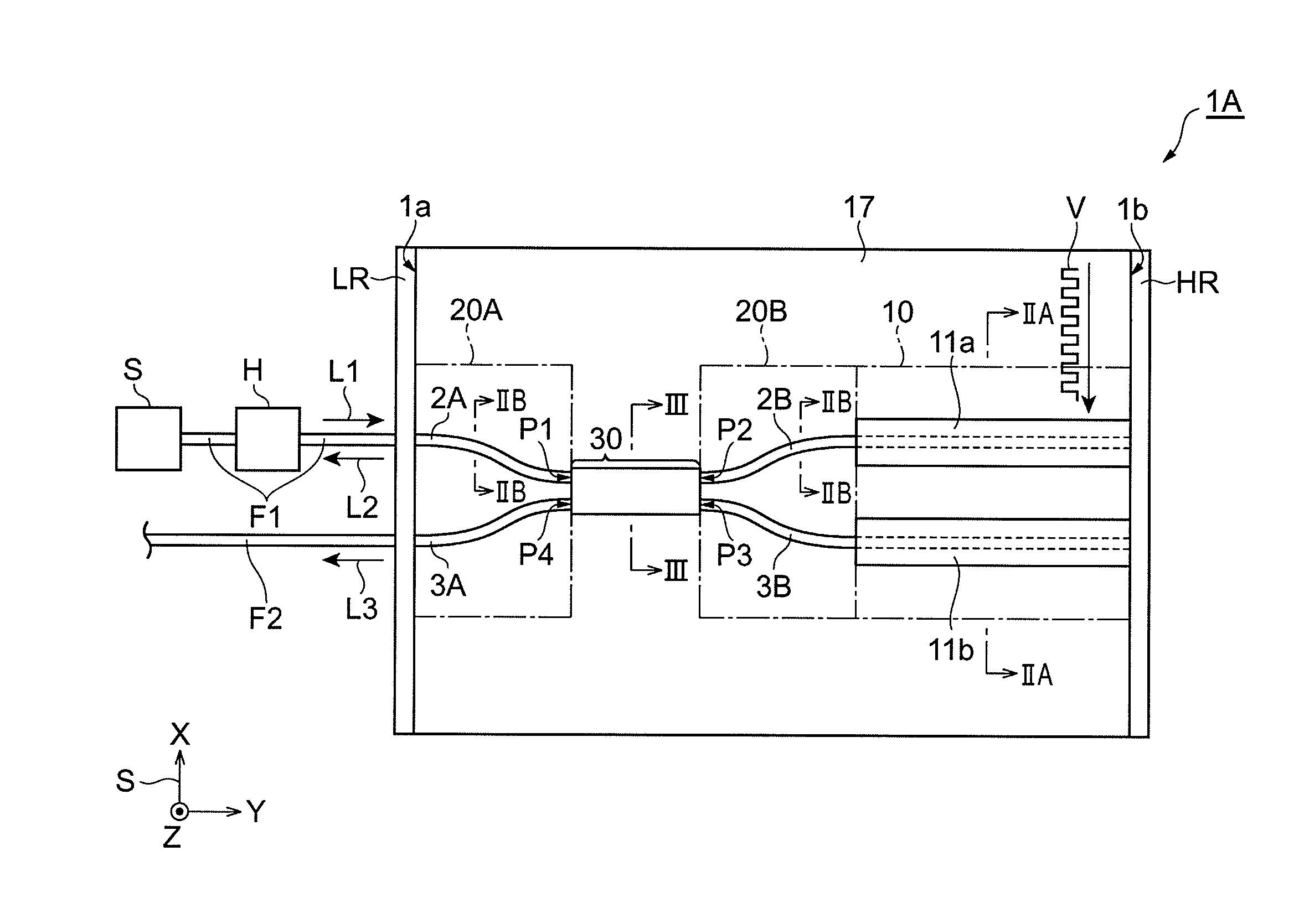
FIG. 1 is a plan view showing an example of a Mach-Zehnder interferometer type optical modulator. Referring to FIG. 1, a Mach-Zehnder interferometer type optical modulator 1A of this embodiment has a first end facet 1a that transmits light and a second end facet 1b that reflects light. The second end facet 1b is the reflecting portion of this embodiment. For example, a high-reflection film HR is formed on the second end facet 1b.

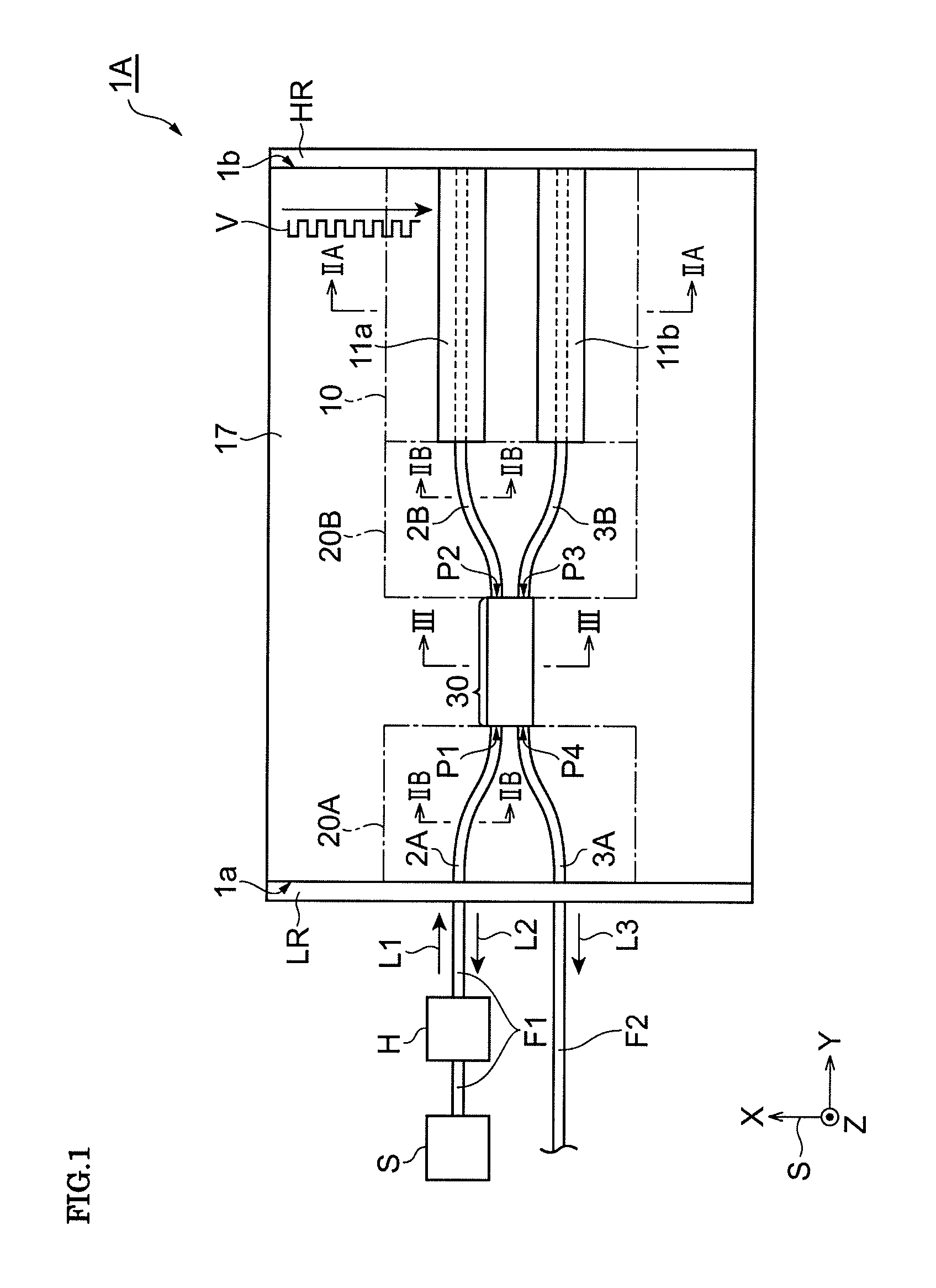
The Mach-Zehnder interferometer type optical modulator 1A of this embodiment includes a phase shifting section 10, waveguiding sections 20A and 20B, and an optical coupler 30. The optical coupler 30 is disposed between the waveguiding section 20A and the waveguiding section 20B. The waveguiding section 20B is disposed between the optical coupler 30 and the phase shifting section 10. The phase shifting section 10, the waveguiding sections 20A and 20B, and the optical coupler 30 are formed on an n-type semiconductor substrate 4 as shown in FIGS. 2A, 2B and 3....

modification example 1

Modification Example 1 of the Mach-Zehnder interferometer type optical modulator 1A described above will now be described. FIG. 4 is a plan view showing Modification Example 1 of a Mach-Zehnder interferometer type optical modulator.

A Mach-Zehnder interferometer type optical modulator 1B shown in FIG. 4 differs from the Mach-Zehnder interferometer type optical modulator 1A shown in FIG. 1 in that the Mach-Zehnder interferometer type optical modulator 1B has a predetermined gap between the phase shifting section 10 and the second end facet 1b. The phase shifting section 10 is disposed apart from the second end facet 1b by the predetermined gap. In other words, the Mach-Zehnder interferometer type optical modulator 1B includes a waveguiding section 20C between the phase shifting section 10 and the second end facet 1b. The waveguiding section 20C extends from the phase shifting section 10 to the second end facet 1b. The waveguiding section 20C includes two optical waveguide structures c...

modification example 2

Modification Example 2 of the Mach-Zehnder interferometer type optical modulator 1A described above will now be described. FIG. 5 is a plan view showing Modification Example 2 of a Mach-Zehnder interferometer type optical modulator. FIG. 6 is a cross-sectional view of the Mach-Zehnder interferometer type optical modulator shown in FIG. 5 taken along line VI-VI.

A Mach-Zehnder interferometer type optical modulator 1C shown in FIGS. 5 and 6 differs from the Mach-Zehnder interferometer type optical modulator 1A shown in FIG. 1 in that a semi-insulating substrate is used as the semiconductor substrate. Accordingly, the structure of a phase shifting section 110 of the Mach-Zehnder interferometer type optical modulator 1C differs from the structure of the phase shifting section 10 of the Mach-Zehnder interferometer type optical modulator 1A.

According to Modification Example 2, an Fe-doped InP substrate may be used as a semi-insulating semiconductor substrate 44. In this case, the lower ele...


PUM

PropertyMeasurementUnit
lengthaaaaaaaaaa
reflectivityaaaaaaaaaa

Abstract

A Mach-Zehnder interferometer type optical modulator includes a first end facet and a reflecting portion opposing the first end facet; a single optical coupler including input and output ports, the optical coupler being disposed between the first end facet and the reflecting portion; first and second optical waveguides that are connected to the input ports of the optical coupler; third and fourth optical waveguides that are connected to the output ports of the optical coupler; and a phase shifting section disposed between the optical coupler and the reflecting portion. The phase shifting section includes a first optical waveguide structure constituting part of the third optical waveguide; a first upper electrode on the first optical waveguide structure; a second optical waveguide structure constituting part of the fourth optical waveguide; and a second upper electrode on the second optical waveguide structure.

Description

BACKGROUND OF THE INVENTION1. Field of the InventionThe present invention relates to Mach-Zehnder interferometer type optical modulators.2. Description of the Related ArtPatent Document 1 (Japanese Unexamined Patent Application Publication No. 62-183406) describes a waveguide-type optical interferometer. This waveguide-type optical interferometer includes a substrate, two optical guides composed of glass or a plastic formed on the substrate, two optical couplers that connect the optical waveguides to each other at different positions, and phase shifters disposed in the optical waveguides between the optical couplers. Each phase shifter includes a heater disposed on the optical waveguide. The optical path length of the optical waveguide is changed by controlling the temperature of the optical waveguide by heating the heater of the phase shifter.In recent years, optical modulators that modulate light in response to electric signals from outside have become one of the essential compone...

Claims


Application Information

Patent Timeline
Patent Type & Authority Applications(United States)
IPC IPC(8): G02F1/035
CPCG02F2001/212G02F2201/34G02F1/225G02F2201/17G02F1/035G02F1/212
Inventor HASHIMOTO, JUN-ICHI
Owner SUMITOMO ELECTRIC IND LTD
Why Eureka
Try Eureka