Method and device for co-ordinating networked group members

Active Publication Date: 2006-04-06
BRITISH TELECOMM PLC
View PDF7 Cites 1 Cited by
  • Summary
  • Abstract
  • Description
  • Claims
  • Application Information

AI Technical Summary

Benefits of technology

[0019] In the case of there being a plurality of other members the waiting channel is preferably a multicast channel. This allows a large number of other members to join the waiting channel without imposing significant signalling overheads on the network.
[0021] Additionally, within the preferred embodiment the messages are preferably Multicast Source Notification of Interest Protocol (MSNIP) messages. Such a protocol provides the advantages of simplicity and low network overheads for its implementation, there being relatively few messages required by such a protocol.
[0038] From a seventh aspect the invention further provides a network channel when used as a waiting channel, wherein members of a group other than a first member join the waiting channel whilst performing an action or process, and then leave the waiting channel once the action or process has been performed, wherein the first member of the group then performs an action or process. Such a network channel facilitates the earlier aspects of the invention as previously described.

Problems solved by technology

In general the technical literature available in the art shows a distinct lack of solutions to control and coordinate a large population of networked devices.
Such features are fine provided that no coordination of the senders and receivers is required, but once such co-ordination becomes necessary then the existing group communication techniques face problems.
However neither of these protocols are able to guarantee coordination between different users since they do not provide any feedback channel.
The main challenge of these mechanisms is to deal with very large and variable sets of population so as to alleviate the problem of implosion on the interface or on the server that is requesting feedback.
However with such an algorithm an initiator may have to spend a lot of resources in terms of bandwidth and cpu processor time.
Furthermore the technique can only give an overall sample of the population because of its statistical nature and network reliability problems.

Method used


Image

  • Method and device for co-ordinating networked group members
  • Method and device for co-ordinating networked group members
  • Method and device for co-ordinating networked group members

Examples


first embodiment

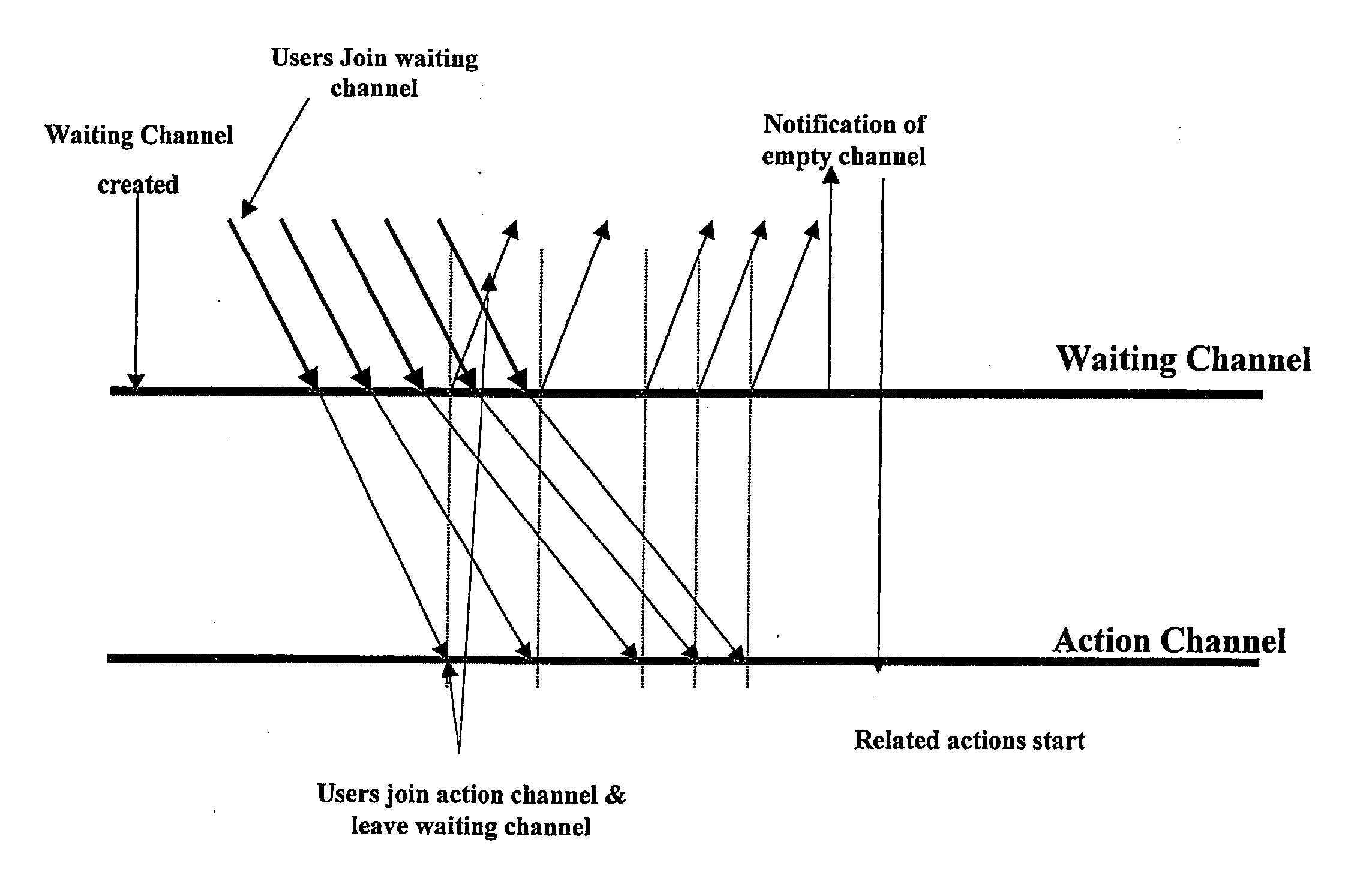
[0080] As an example of the above described operation, we now consider a first embodiment, which will be described with reference to FIGS. 5 and 6.

[0081] Within the first embodiment we virtually divide the available communications channels into two sets: waiting channels and main channels. Here, a receiver joins a waiting channel whilst waiting an action to start on an action channel, and then leaves the channel to join the action channel when the receiver is ready for the action to start—in other words leaving a waiting channel triggers an action on an action channel. As a result the waiting and action state is only dynamically associated, and it is possible that an action channel once triggered may then serve in turn as a waiting channel for another action channel. It is important to notice that the terms action channel is not directly associated with a communication channel, it could even be a simple action performed exploiting this mechanism.

[0082] As an example of the above, a...

second embodiment

[0088] A second embodiment which illustrates how the invention may be used in supply chain management or project management will now be described with respect to FIG. 7.

[0089]FIG. 7 illustrates a number of tasks which need to be completed within a given project, and the interrelationships between each task which govern the order in which they need to be completed. As an example, consider task E. Here, it will be seen that task E needs to be completed serially after all of tasks A, B, and C have finished, but that tasks A, B, and C may themselves be conducted in parallel (with task D, in addition). Another example is Task I, which must be completed serially after Tasks G and H have completed, but may be completed in parallel with Tasks L and M.

[0090] It is important to note here that the tasks illustrated in FIG. 7 may be almost any task. For example, the overall process shown in FIG. 7 might relate to the design of a new building or aircraft, or to the manufacture of a new car. Alt...

third embodiment

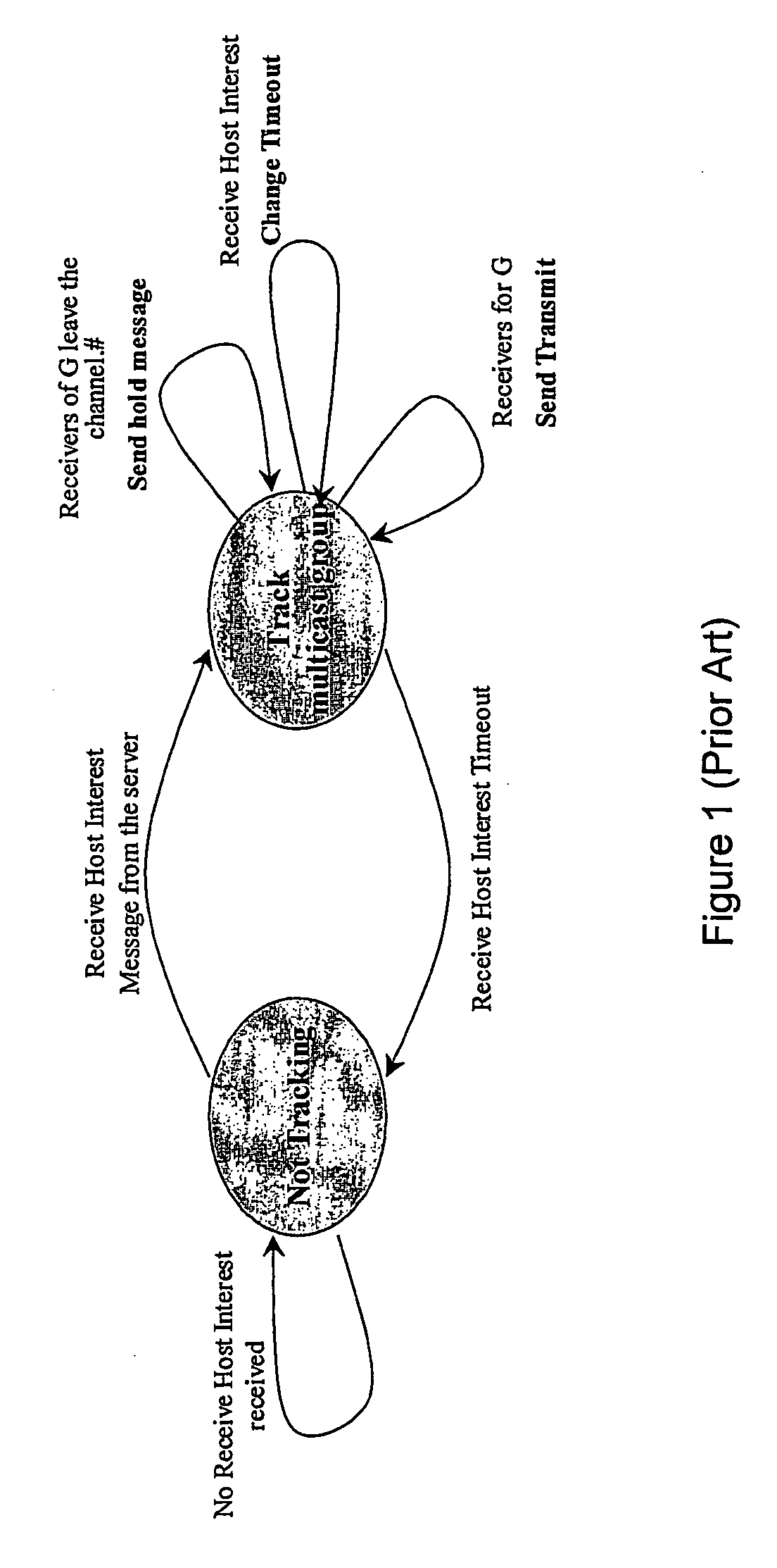
[0096] In order to address this problem, in a third embodiment we provide a solution to this problem by implementing a secure version of the IGMP protocol implemented in the access router. Here, a host's IGMP requests need to be authenticated before a router triggers the multicast routing protocol. This gives liability to edge routers for each host they accept. In order to extend such a mechanism to the co-ordination techniques of the present invention we associate to each receiver application which wishes to participate in a group communication a key message. A receiver application is then only allowed to join a waiting channel if it is able to authenticate itself by passing to the IGMP router the correct information. By exploiting such a mechanism we are able to protect against malicious join events (a malicious join event being by a malicious user who has no intention of leaving the waiting channel, hence effectively performing a Denial of Service attack on the other receivers), ...


PUM


Abstract

The invention provides the concept of a network channel which is used as a waiting channel, wherein members of a group other than a first member join the waiting channel whilst performing an action or process, and then leave the waiting channel once the action or process has been performed. Once all of the members have left the waiting channel the first member of the group then performs an action or process. In order to indicate to the first member that all of the other members have left the waiting channel, a protocol such as the Multicast Source Notification of Interest Protocol (MSNIP) may be used.

Description

TECHNICAL FIELD [0001] The present invention relates to a method for co-ordinating the actions of a group of users, applications, or devices who communicate via a network, and to devices which are capable of performing such a method. BACKGROUND TO THE INVENTION [0002] With this invention the general problem that we are trying to solve is that of coordination between a different numbers of receivers, or alternatively, if we describe the problem as a temporal process model then the problem becomes the coordination of different activities that participate in the achievement of a final objective. [0003] In general the technical literature available in the art shows a distinct lack of solutions to control and coordinate a large population of networked devices. Network scenarios where a sender is able to contact a large number of receivers using a single communication channel are known, and in general the protocol used to achieve this goal is IP-Multicast, although in the last few years o...

Claims


Application Information

Patent Timeline
IPC IPC(8): G06F15/16G06Q10/00H04L12/18
CPCG06Q10/10H04L12/1822
Inventor BURBRIDGE, TREVORSOPPERA, ANDREABRISCOE, ROBERT J.JACQUET, ARNAUD
Owner BRITISH TELECOMM PLC
Why Eureka
Try Eureka