Successive pyrolysis system of waste synthetic-highly polymerized compound

a pyrolysis system and high-polymer technology, applied in the direction of combustible gas coke oven heating, charging-discharging device combination, products, etc., can solve the problems of high heat transfer, many difficulties in the pyrolysis system type, and achieve the effect of maximizing the operating rate of the pyrolysis devi

Inactive Publication Date: 2006-04-13
ALPO
View PDF10 Cites 39 Cited by
  • Summary
  • Abstract
  • Description
  • Claims
  • Application Information

AI Technical Summary

Benefits of technology

[0011] Therefore, the object of the present invention is to provide a successive pyrolysis system of waste synthetic-highly polymerized compound that maximizes the operating rate of the pyrolysis device by successively injecting a predetermined amount of waste and successively discharging ashes exhausted after going through the pyrolysis process, when pyrolizing waste synthetic-highly polymerized compound like waste plastics by indirect heating in a pyrolysis chamber, in which a high-temperature and anaerobic or hypoxic environment is maintained.

Problems solved by technology

The batch-type pyrolysis system involves many difficulties in pyrolizing waste, in which various materials are mixed.
Especially, when foreign materials (glassware, earth, nonferrous metals, etc.) are mixed, heat transfer is not smoothly performed, and there is limit in producing refined oil from the waste by the pyrolysis, and thus utility value thereof is very small.
Therefore, there is a problem that the piping that connects the pyrolysis chamber and the distillation column is damaged or broken down.

Method used


Image

  • Successive pyrolysis system of waste synthetic-highly polymerized compound
  • Successive pyrolysis system of waste synthetic-highly polymerized compound
  • Successive pyrolysis system of waste synthetic-highly polymerized compound

Examples


Embodiment Construction

[0042] Preferred embodiments of the present invention will be explained in detail on below, which is to explain the present invention in detail to the extent that one skilled in the art may easily work the invention, and does not limit the technical idea and scope of the present invention.

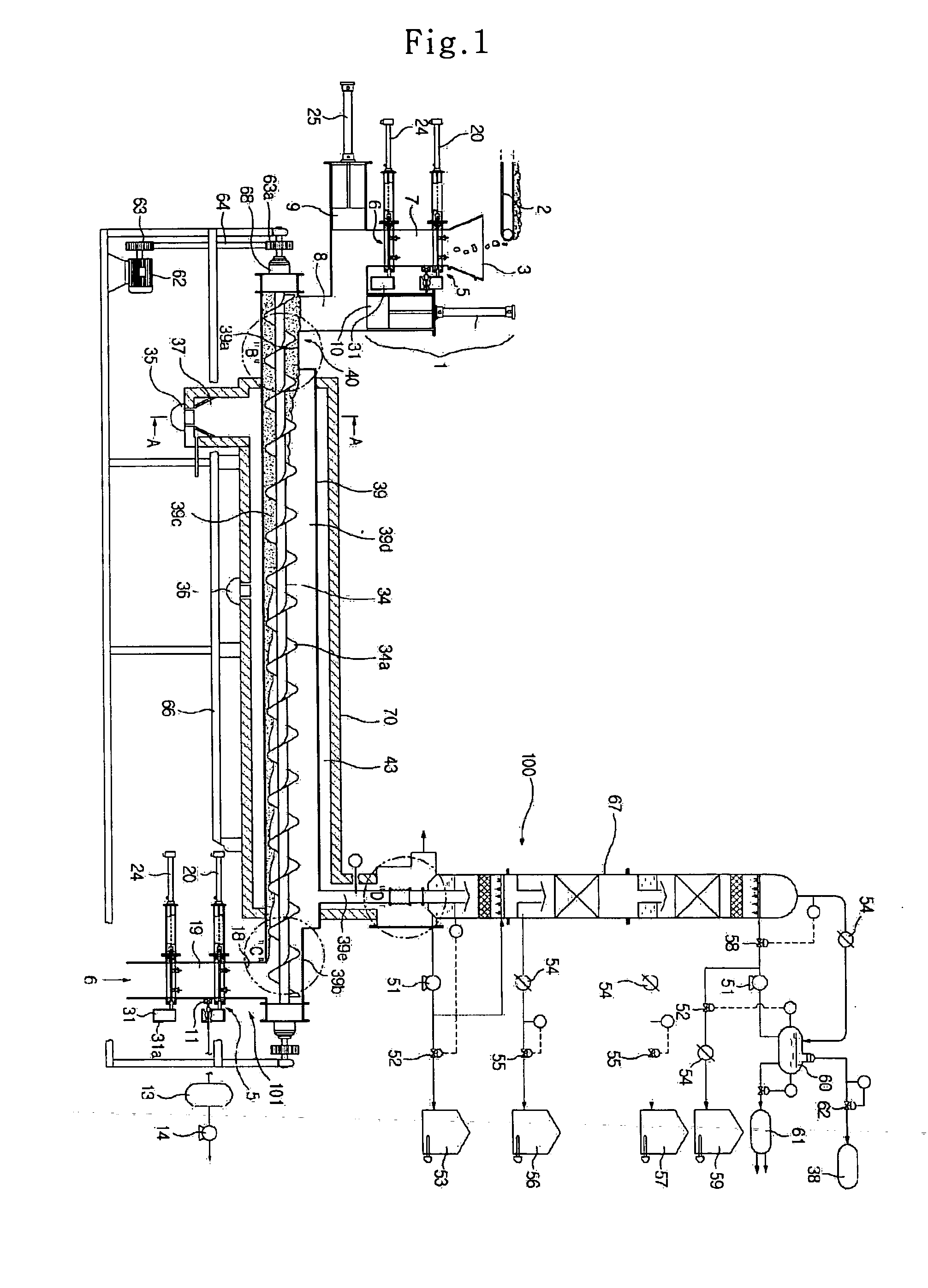
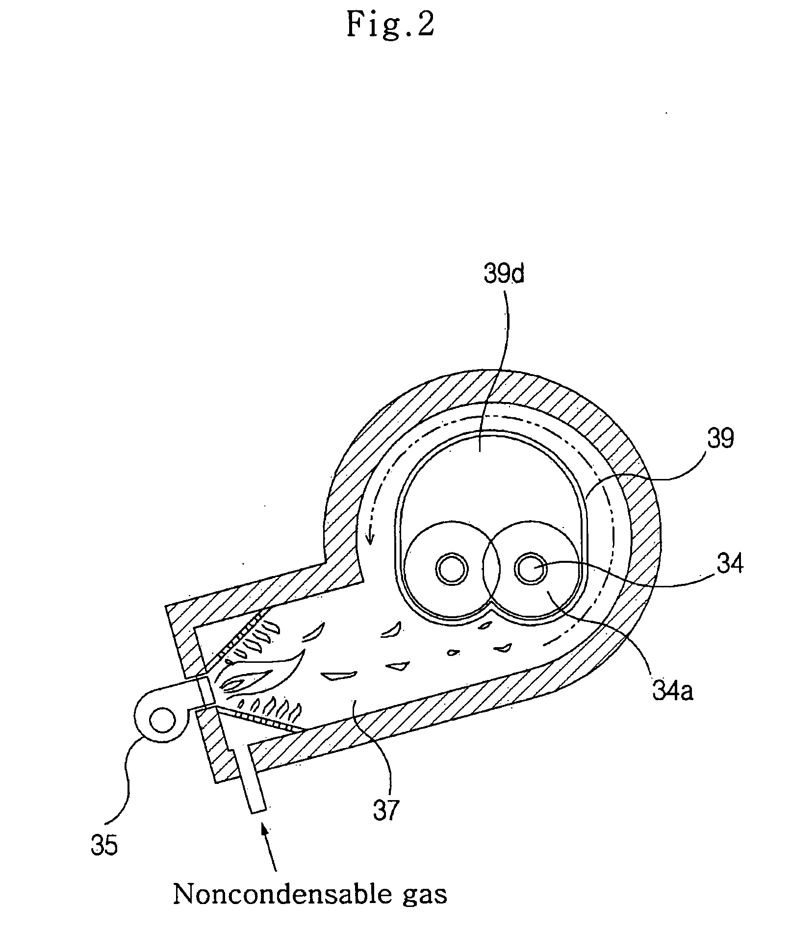
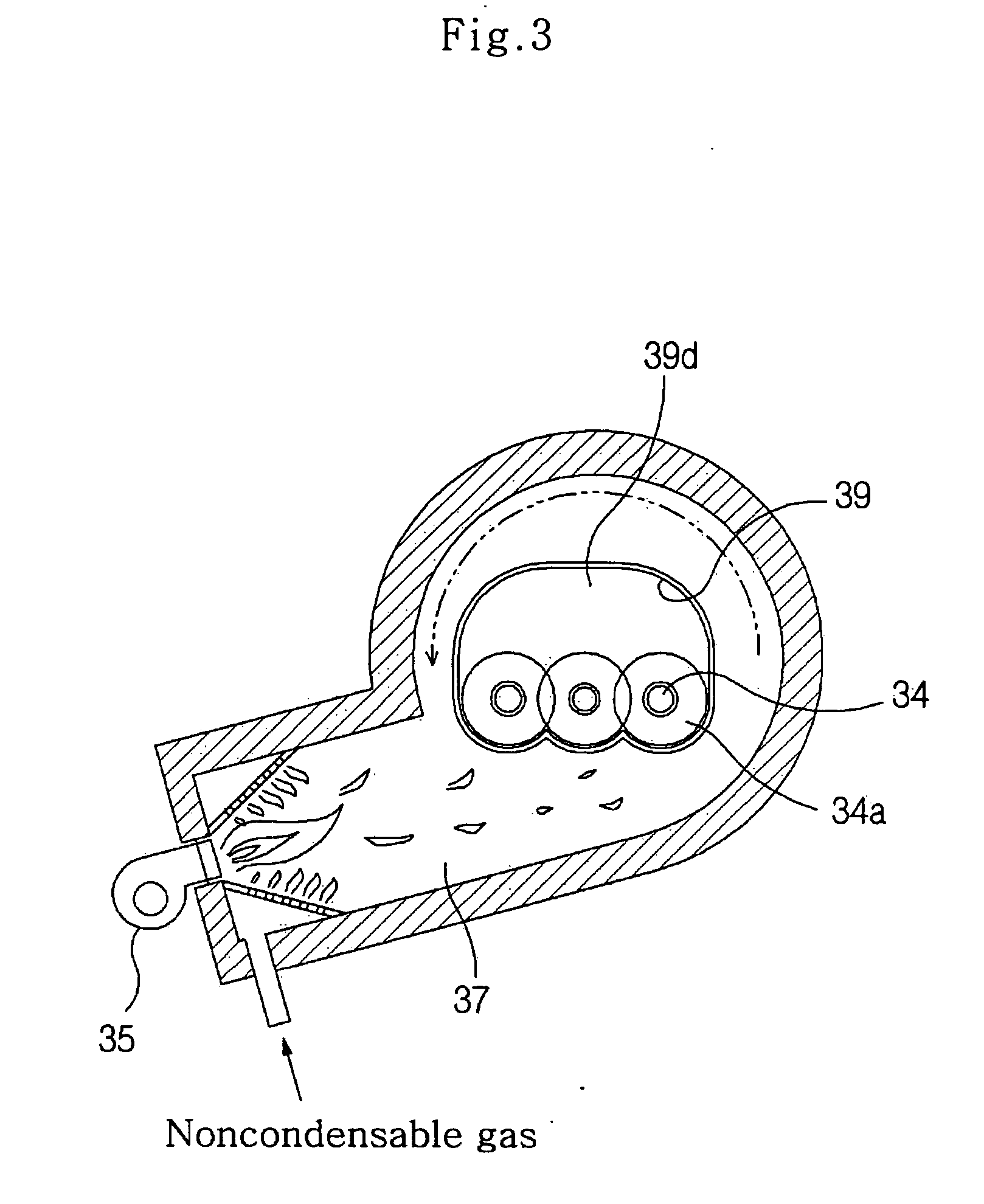
[0043] As illustrated in FIGS. 1-12, the successive pyrolysis system of waste synthetic-highly polymerized compound in accordance with the present invention comprises a hopper 3, which the waste is provided to and is stored in a predetermined amount; an automatic waste injection device 1, which automatically discharges a predetermined amount of waste from the hopper 3, and comprises an air removing means for maintaining a hypoxic environment inside by removing external air flowing in along with the waste; a pyrolysis chamber 39 for maintaining a high-temperature (250-450° C.) and hypoxic environment, and successively pyrolizing the waste by indirect heating, in which two or more transport screws 3...


PUM

PropertyMeasurementUnit
temperatureaaaaaaaaaa
timeaaaaaaaaaa
temperatureaaaaaaaaaa

Abstract

Disclosed is a successive pyrolysis system of waste synthetic-highly polymerized compound for successively pyrolizing combustible waste by indirect heating at a pyrolysis chamber maintaining an anaerobic or hypoxic environment, and producing refined oil like heavy oil and light oil according to boiling points at a distillation column to be used as heat source for the pyrolysis of the waste. The successive pyrolysis system comprises a hopper; an automatic waste injection device, which discharges a predetermined amount of waste from the hopper; a pyrolysis chamber for maintaining a high-temperature and hypoxic environment, and successively pyrolizing the waste by indirect heating; a gas burning chamber for burning noncondensable gas among pyrolysis gas produced at the time of the pyrolysis of the waste, and providing heat of a predetermined temperature to the outer surface of the pyrolysis chamber to be used as heat source for the pyrolysis of the waste; a refined oil producing means for producing refined oil from the pyrolysis gas reformed after going through catalyst reaction and providing residual noncondensable gas to the gas burning chamber; and an automatic discharging device for successively discharging ashes transported after being pyrolized from the pyrolysis chamber.

Description

CROSS-REFERENCE TO RELATED APPLICATIONS [0001] This application claims benefit under 35 U.S.C. §119 from Korean Patent Application No. 2004-77580, filed on Sep. 25, 2004, the entire content of which is incorporated herein by reference. BACKGROUND OF THE INVENTION [0002] 1. Field of the Invention [0003] The present invention relates to a successive pyrolysis system of waste synthetic-highly polymerized component to successively pyrolize combustible waste like waste plastics by indirect heating at a pyrolysis chamber, in which an anaerobic or hypoxic environment is maintained, and produce refined oil like heavy oil and light oil according to boiling points at a distillation column to be used as heat source for the pyrolysis of the waste. [0004] 2. Description of the Related Art [0005] More particularly, the present invention relates to a successive pyrolysis system of waste synthetic polymerized component, which simultaneously performs the processes of successively desiccating, meltin...

Claims


Application Information

Patent Timeline
Patent Type & Authority Applications(United States)
IPC IPC(8): C10B49/00C10B51/00C10B35/00
CPCC10B47/44C10B53/07C10G1/10Y02P20/143
Inventor KU, JAE WAN
Owner ALPO
Why Eureka
Try Eureka