
Method and device for selecting between internal and external antennas

a technology of internal and external antennas, applied in the field of rf frontend arrangement of mobile phones, can solve the problems of increasing introducing additional losses, and affecting the operation of the system, so as to reduce the number of series switches

Active Publication Date: 2006-04-13
NOKIA TECHNOLOGLES OY
View PDF6 Cites 71 Cited by
  • Summary
  • Abstract
  • Description
  • Claims
  • Application Information

AI Technical Summary

Benefits of technology

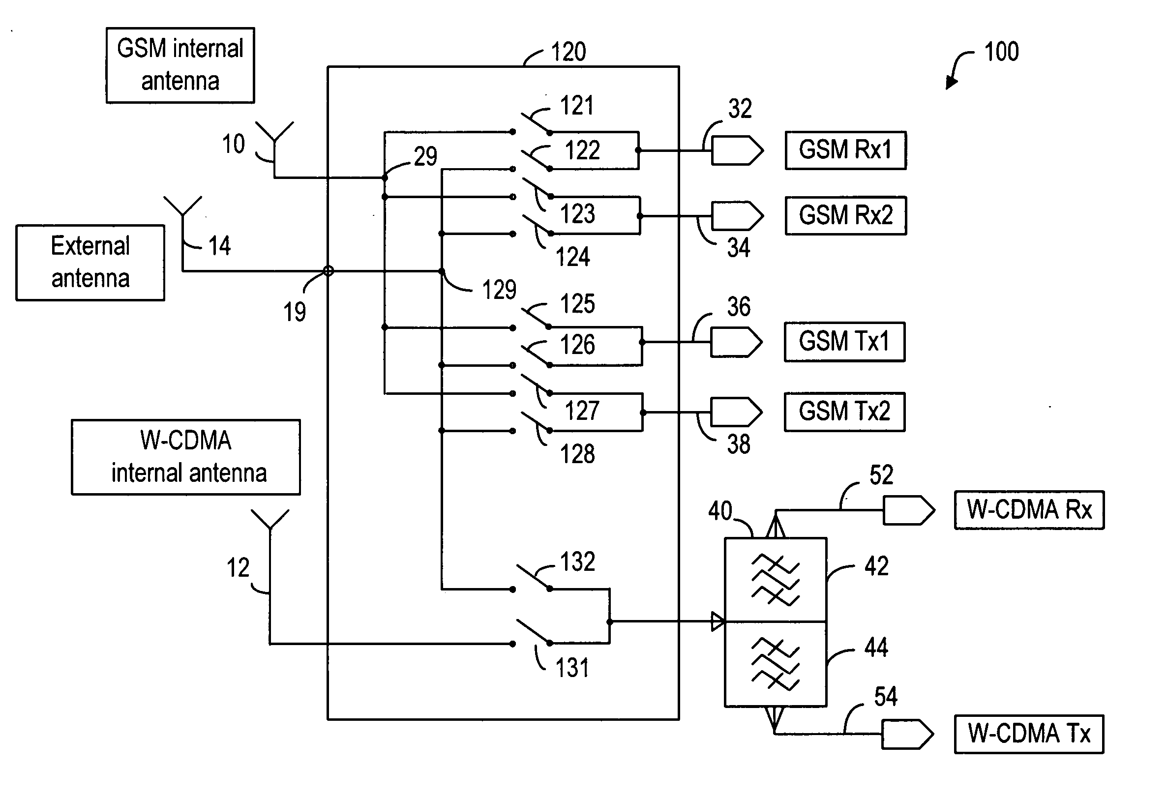
[0007] The present invention-uses an antenna switch part in which two series path selection components or switches are used to operatively connect to the same connection point in each signal path. These two series switches are separately connected to two different antennas for selecting one of the antennas in order to route the signals in that signal path. In effect, the two switches for each signal path are connected in parallel. In a mobile terminal that has N signal paths, 2N series switches are used to select the antennas as well as the signal paths. However, where the frequency range difference between two signal paths are small such that bandpass filters or phase shifters can be used for path selections, the number of series switches can be reduced.

Problems solved by technology

Putting an additional path selection component in the signal path introduces additional losses.
The losses are especially critical in the W-CDMA case.
The losses associated with these types of solid-state switches are generally quite significant.
Although one could use mechanical switches to reduce the losses, the size of mechanical switches renders their usage impractical.

Method used


Image

  • Method and device for selecting between internal and external antennas
  • Method and device for selecting between internal and external antennas
  • Method and device for selecting between internal and external antennas

Examples


Embodiment Construction

[0048] The present invention uses a pair of switching elements equivalent to a SP2T switch to connect to each transmit path and each receive path except where a transmit and receive path pair can be selected through bandpass filters and phase shifters. In the latter case, the transmit and receive path pair can share a SP2T switch. One of the switch elements in each SP2T switch arrangement is connected to an internal antenna and the other is connected to an external antenna. As shown in FIG. 3a, in addition to two internal antennas 10, 12, an external antenna 14 is also used for signal transmission and reception. In order to select between external and internal antennas, two series switches 121, 122 are connected to the signal path 32 in parallel. Likewise, each of the series switch pairs (123, 124), (125, 126) and (127, 128) is connected to one of the signal paths 34, 36 and 38 in parallel. The switch pair (131, 132) is connected to the duplexer 40. As in the prior art switch arrang...


PUM


Abstract

In an RF front-end having a plurality of signal paths connectable to an internal antenna or an external antenna, an antenna switch part is used to select either the internal or the external antenna. In the antenna switch part, two series switches are used to operatively connect to the same connection point in each signal path. These two series switches are separately connected to two different antennas for selecting one of the antennas in order to route the signals in that signal path. For providing further isolation between signal paths, each signal path can be connected to a shunt switch near the connection point. Only the shunt switch connected to the selected signal path is operated in an open position, all the other shunt switches are operated in a closed position.

Description

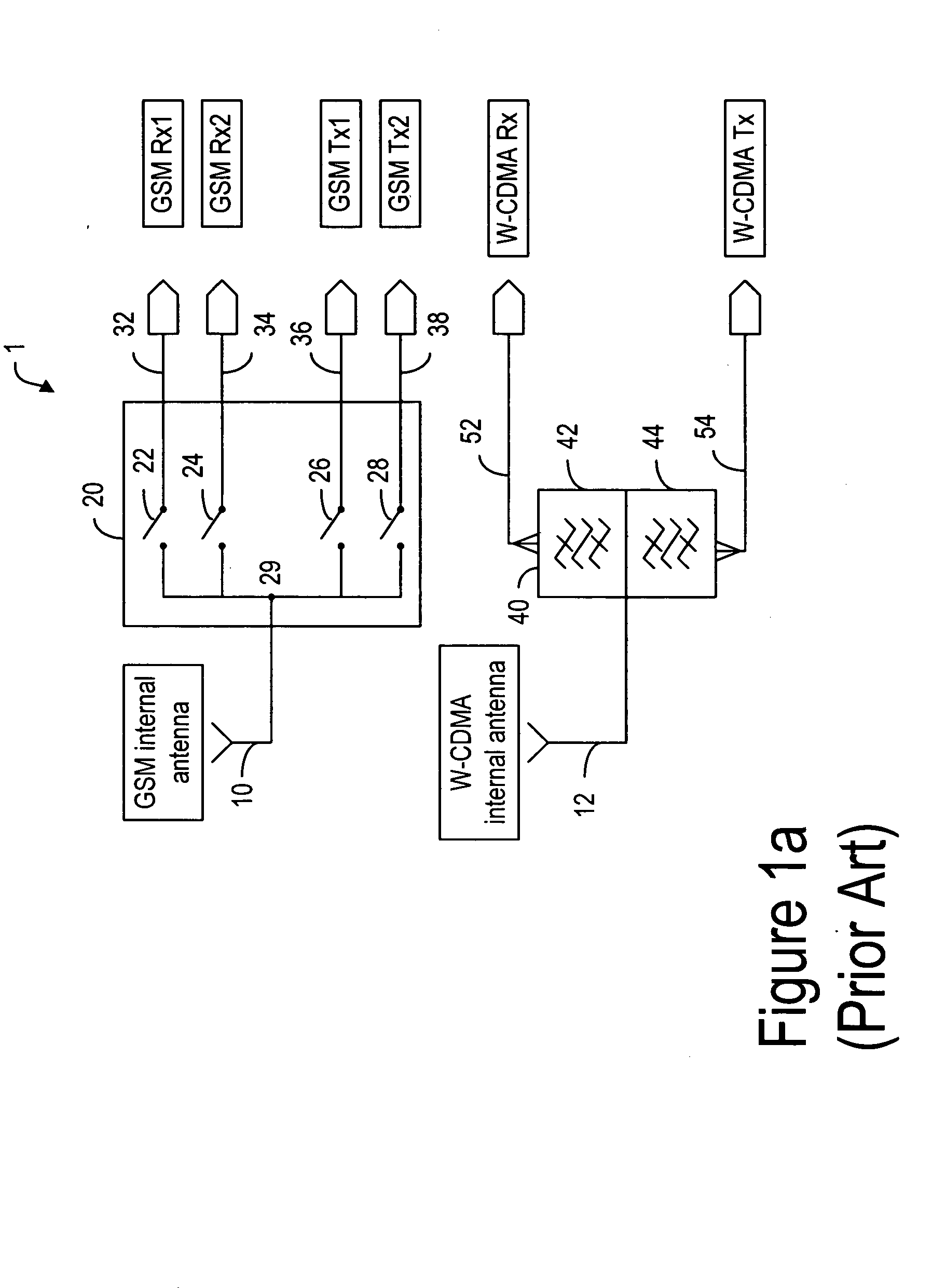
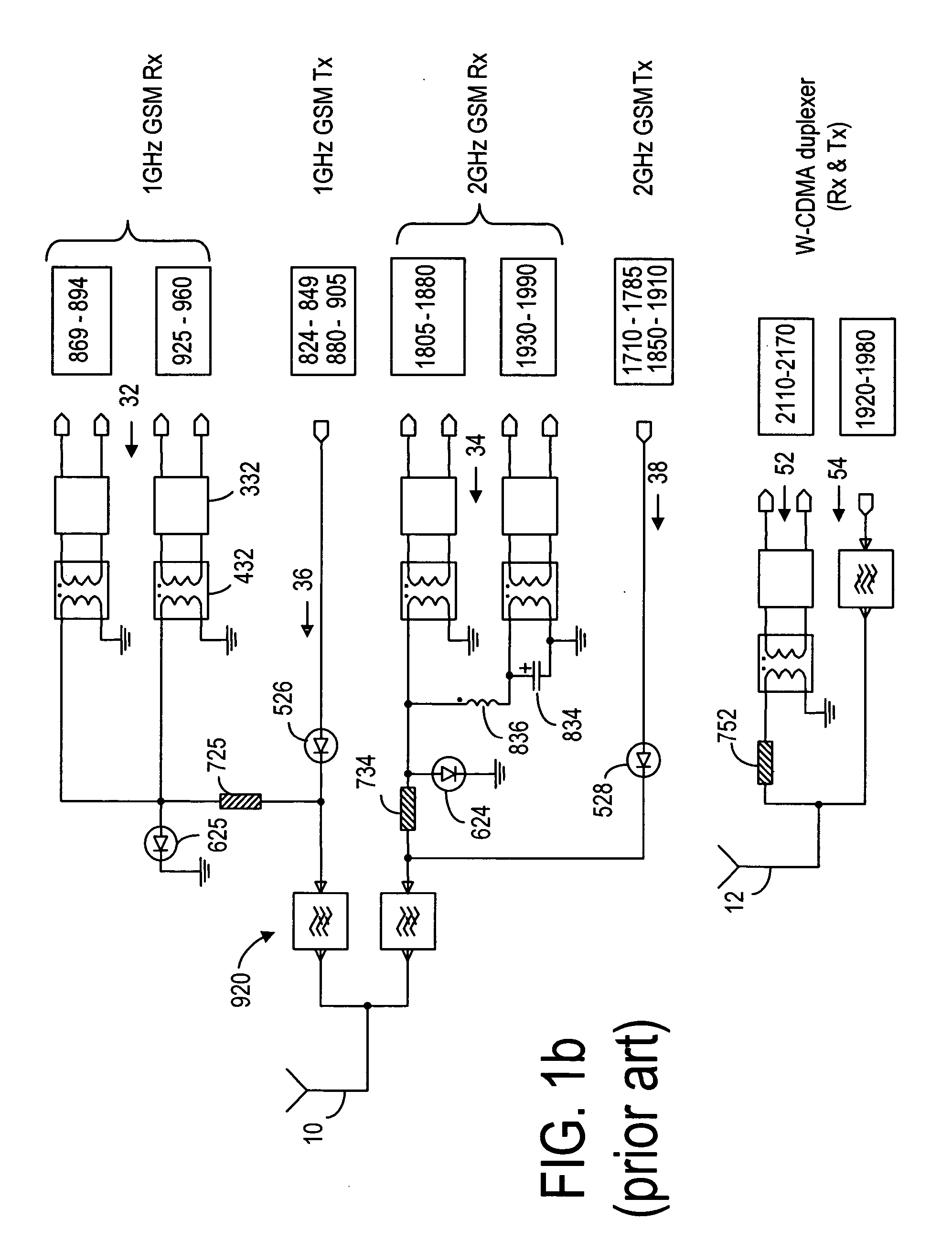
FIELD OF THE INVENTION [0001] The present invention relates generally to RF front-end arrangement of a mobile phone and, more particularly, to the switching arrangement in a mobile phone front-end. BACKGROUND OF THE INVENTION [0002] When a mobile phone is operable in many different frequency bands, such as GSM and W-CDMA bands, the RF front-end of the mobile phone generally has a plurality of switches for selecting among those bands. For example, a mobile phone is operable in a plurality of GSM bands and one W-CDMA band, it has two antennas: one GSM antenna 10 and one W-CDMA antenna 12, as shown in FIG. 1a. The front-end module 1 includes an antenna switch 20 having a plurality of series switches 22, 24, 26 and 28 operatively connected to the GSM signal paths 32, 34, 36, and 38 so as to allow the GSM signals to be routed through the GSM antenna 10 through a common node 29. In addition, a duplexer 40 having a bandpass filter 42 and a bandpass filter 44 operatively connected to the W-...

Claims


Application Information

Patent Timeline
IPC IPC(8): H04M1/00H04B1/44
CPCH04B1/006
Inventor ELLA, JUHAKOJOLA, ILKKA TARMO
Owner NOKIA TECHNOLOGLES OY
Learn More