Controlling electronic withdrawals by a transaction processor

a transaction processor and electronic withdrawal technology, applied in the field of data processing, can solve the problems of electronic withdrawal, limit on withdrawal type, withdrawal period, maximum withdrawal amount,

Active Publication Date: 2006-04-13
TOSHIBA GLOBAL COMMERCE SOLUTIONS HLDG
View PDF1 Cites 6 Cited by
  • Summary
  • Abstract
  • Description
  • Claims
  • Application Information

AI Technical Summary

Benefits of technology

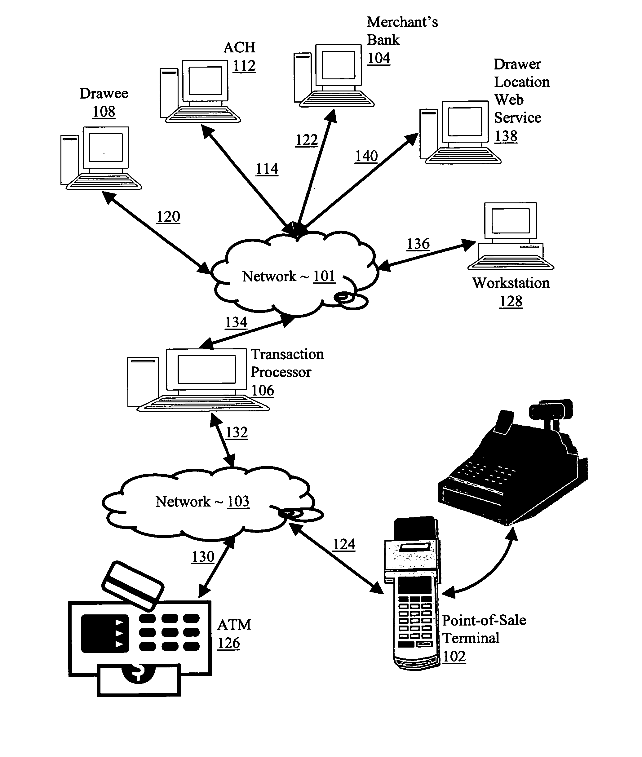
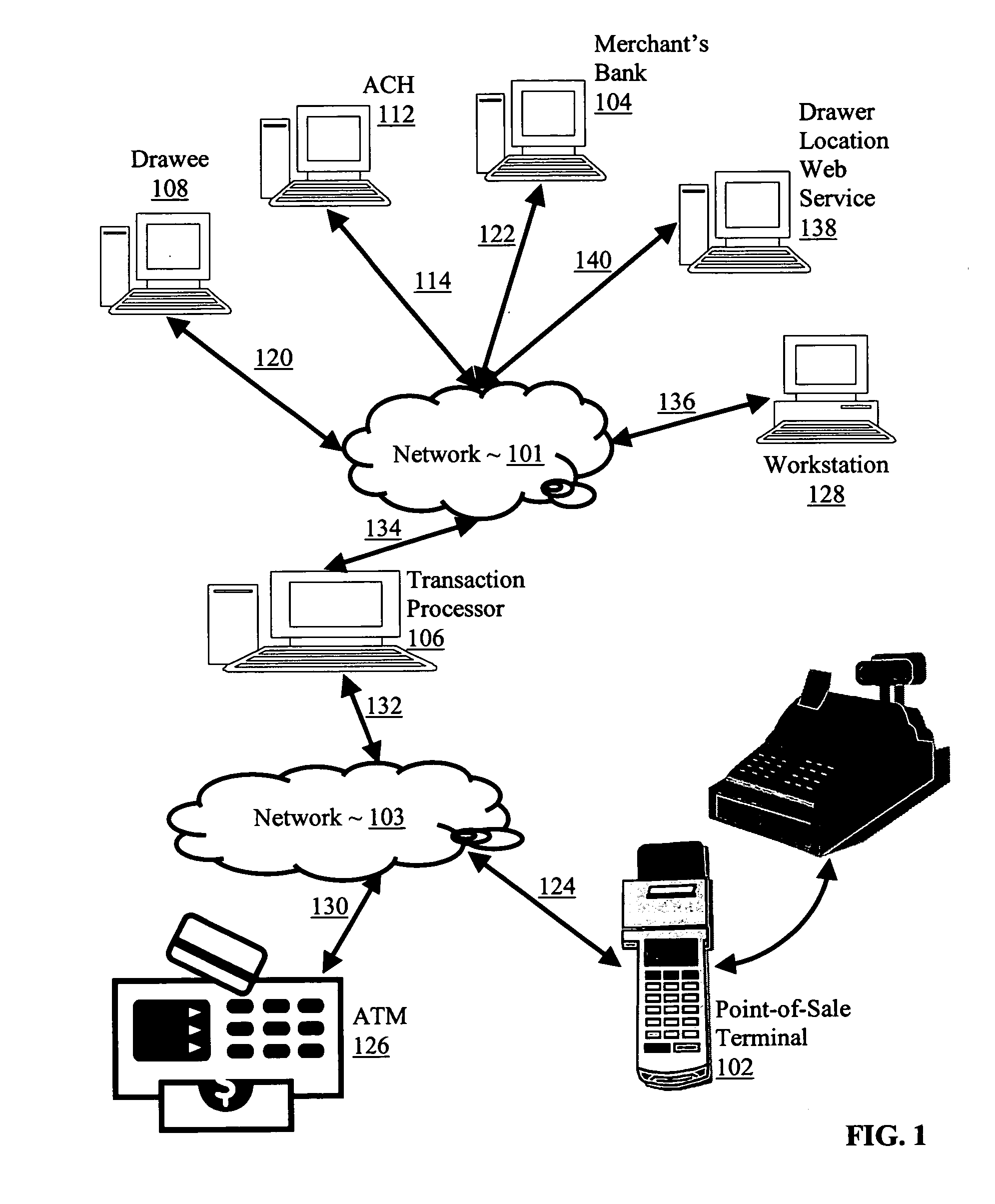
[0022] Exemplary methods, systems, and products are disclosed for controlling electronic withdrawals by a transaction processor that include receiving in the transaction processor from a withdrawal device a withdrawal request, where the withdrawal request includes a withdrawal device identifier, a drawer identifier, a drawee identifier, and a withdrawal amount; transmitting from the transaction processor to a drawee a request for limitations on electronic withdrawals for the drawer, where the limitations include a limitation on drawer location; receiving in the transaction processor from storage in computer memory of the drawee data representing the limitations on electronic withdrawals for the drawer, including the limitation on drawer location; and authorizing, by the transaction processor, an electronic withdrawal in dependence upon the limitations, including the limitation on drawer location. In typical embodiments, the limitations on electronic withdrawals may include limitations on withdrawal type, account, withdrawal period, and maximum withdrawal amount. In typical embodiments, the limitation on drawer location may include a geographic area that includes one or more locations of withdrawal devices.
[0023] Typical embodiments include establishing the limitations on electronic withdrawals in the drawee, includ...

Problems solved by technology

In typical embodiments, the limitations on electronic withdrawals may include lim...

Method used


Image

  • Controlling electronic withdrawals by a transaction processor
  • Controlling electronic withdrawals by a transaction processor
  • Controlling electronic withdrawals by a transaction processor

Examples


Embodiment Construction

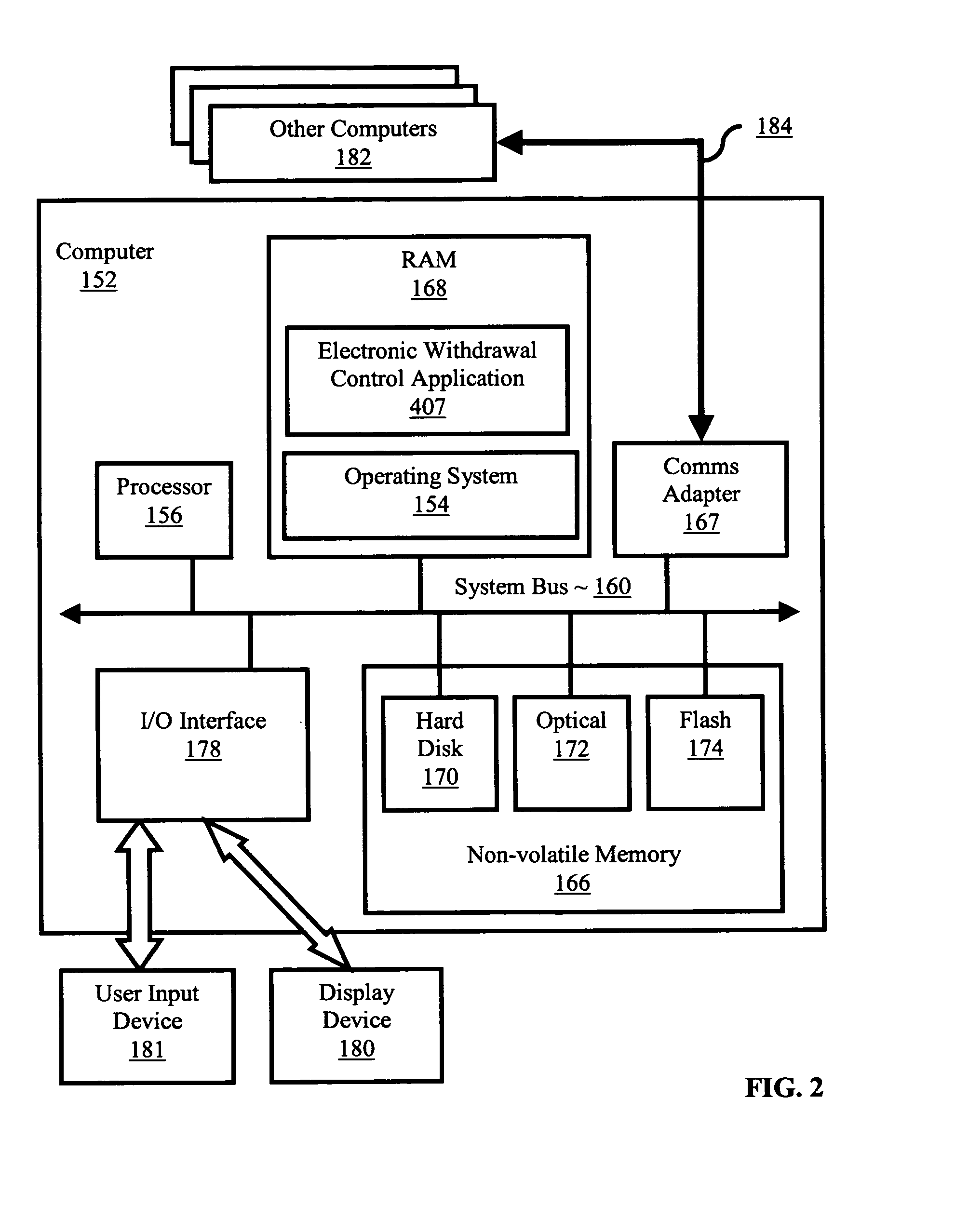
[0032] The present invention is described to some extent in this specification in terms of methods for controlling electronic withdrawals by a transaction processor. Persons skilled in the art, however, will recognize that any computer system that includes suitable programming means for operating in accordance with the disclosed methods also falls well within the scope of the present invention. Suitable programming means include any means for directing a computer system to execute the steps of the method of the invention, including for example, systems comprised of processing units and arithmetic-logic circuits coupled to computer memory, which systems have the capability of storing in computer memory, which computer memory includes electronic circuits configured to store data and program instructions, programmed steps of the method of the invention for execution by a processing unit.

[0033] The invention also may be embodied in a computer program product, such as a diskette or othe...


PUM


Abstract

Controlling electronic withdrawals by a transaction processor including receiving in the transaction processor from a withdrawal device a withdrawal request, where the withdrawal request includes a withdrawal device identifier, a drawer identifier, a drawee identifier, and a withdrawal amount; transmitting from the transaction processor to a drawee a request for limitations on electronic withdrawals for the drawer, where the limitations include a limitation on drawer location; receiving in the transaction processor from storage in computer memory of the drawee data representing the limitations on electronic withdrawals for the drawer, including the limitation on drawer location; and authorizing, by the transaction processor, an electronic withdrawal in dependence upon the limitations, including the limitation on drawer location.

Description

CROSS-REFERENCE TO RELATED APPLICATIONS [0001] The present application is related to the following co-pending applications: [0002] (1) U.S. patent application Ser. No. ______ (Attorney Docket No. AUS920040708US1); [0003] (2) U.S. patent application Ser. No. ______ (Attorney Docket No. AUS920040464US1);BACKGROUND OF THE INVENTION [0004] 1. Field of the Invention [0005] The field of the invention is data processing, or, more specifically, methods, systems, and products for controlling electronic withdrawals by a transaction processor. [0006] 2. Description of Related Art [0007] Electronic withdrawals are typically effected through a withdrawal device such as an Automatic Teller Machine (‘ATM’) and Point-of-Sale (‘POS’) Terminals. An ATM is an electronic device that allows a customer to make cash withdrawals and check account balances at any time without the need for a human teller. Many ATMs also allow people to deposit cash or checks, transfer money between bank accounts, or even buy...

Claims


Application Information

Patent Timeline
IPC IPC(8): G06Q40/00
CPCG06Q20/108G06Q20/1085G06Q40/02
Inventor KEOHANE, SUSANN MARIEMCBREARTY, GERALD FRANCISMULLEN, SHAWN PATRICKMURILLO, JESSICASHIEH, JOHNNY MENG-HAN
Owner TOSHIBA GLOBAL COMMERCE SOLUTIONS HLDG
Why Eureka
Try Eureka