Optical element molding method and apparatus

Inactive Publication Date: 2006-04-20
NIKON CORP
View PDF0 Cites 1 Cited by
  • Summary
  • Abstract
  • Description
  • Claims
  • Application Information

AI Technical Summary

Benefits of technology

[0015] It is an object of the present invention to reduce errors in the shapes of the final molding space easily and surely.
[0016] According to one aspect of an optical element molding method of the present invention, a material for an optical element is accommodated between a first mold and a second mold, and is pressurized to mold the optical element having a predetermined shape by relatively moving the first mold and the second mold while the material is heated to a predetermined temperature. This method includes the steps of determining, as a molding-reference distance, a distance between the first mold and the second mold of when a molding pressure which is generated between the first mold and the second mold applied to the material reaches a predetermined pressure, and moving either one of the first mold and the second mold from the molding-reference distance by a predetermined distance, thereby finishing molding of the optical element. Therefore, it is possible to reduce errors in the shapes of the final molding space easily and surely.
[0019] Another aspect according to the optical element molding method of the present invention includes the steps of determining, as a molding-reference position, a position of the second mold of when a molding pressure which is generated between the first mold and the second mold applied to the material reaches a predetermined pressure, and moving the second mold from the molding-reference position by a predetermined distance, thereby finishing molding of the optical element. Therefore, it is possible to reduce errors in the shapes of the final molding space easily and surely.
[0020] According to an aspect of an optical element molding apparatus of the present invention, a control unit determines, as a molding-reference distance, a distance between a first mold and a second mold of when a pressure detected by a pressure detecting unit reaches a predetermined pressure, and controls the mold moving unit to move either one of the first mold and the second mold from the molding-reference distance by a predetermined distance. Therefore, it is possible to reduce errors in the shapes of a final molding space formed by the first mold and the second mold easily and surely.
[0023] According to still another aspect of the optical element molding apparatus of the present invention, a control unit determines, as a molding-reference position, a position of the second mold of when a pressure detected by a pressure detecting unit reaches a predetermined pressure, and controls a mold moving unit to move the second mold from the molding-reference position by a predetermined distance. Therefore, it is possible to reduce errors in the shapes of the final molding space formed by the first mold and the second mold easily and surely.
[0024] According to still another aspect of the optical element molding apparatus of the present invention, the control unit includes a pressure setting unit that sets the predetermined pressure. Therefore, it is possible to easily and surely mold the optical element with higher precision by adjusting a value of a molding-reference pressure in accordance with the shape of the optical element to be molded.

Problems solved by technology

However, processing of the molds requires a lot of time in order to make the heights of all the molds the same with high precision.
Moreover, management of the molds is troublesome when the parameter for absorbing the error is given to the control device.

Method used


Image

  • Optical element molding method and apparatus
  • Optical element molding method and apparatus
  • Optical element molding method and apparatus

Examples


first embodiment

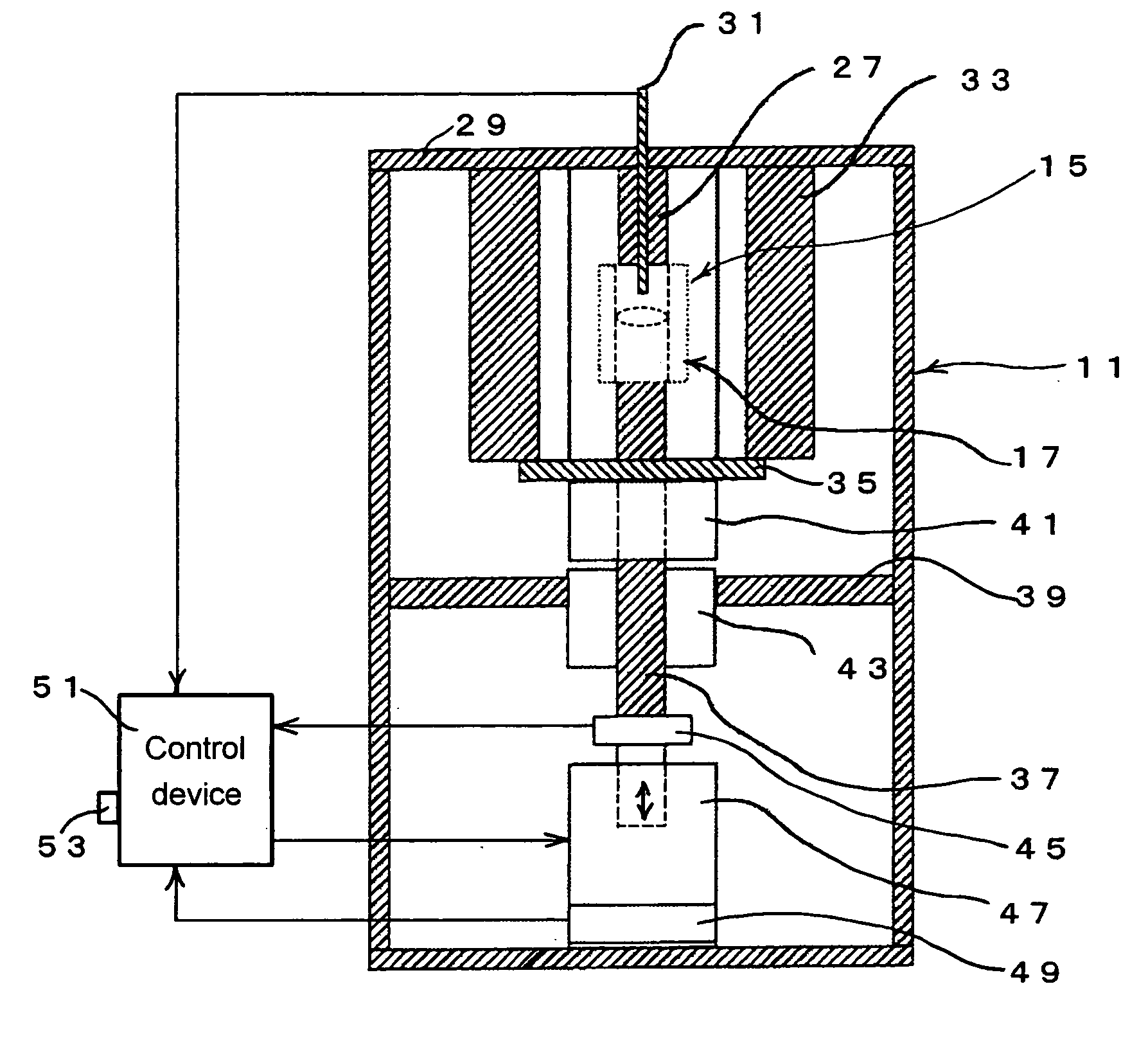
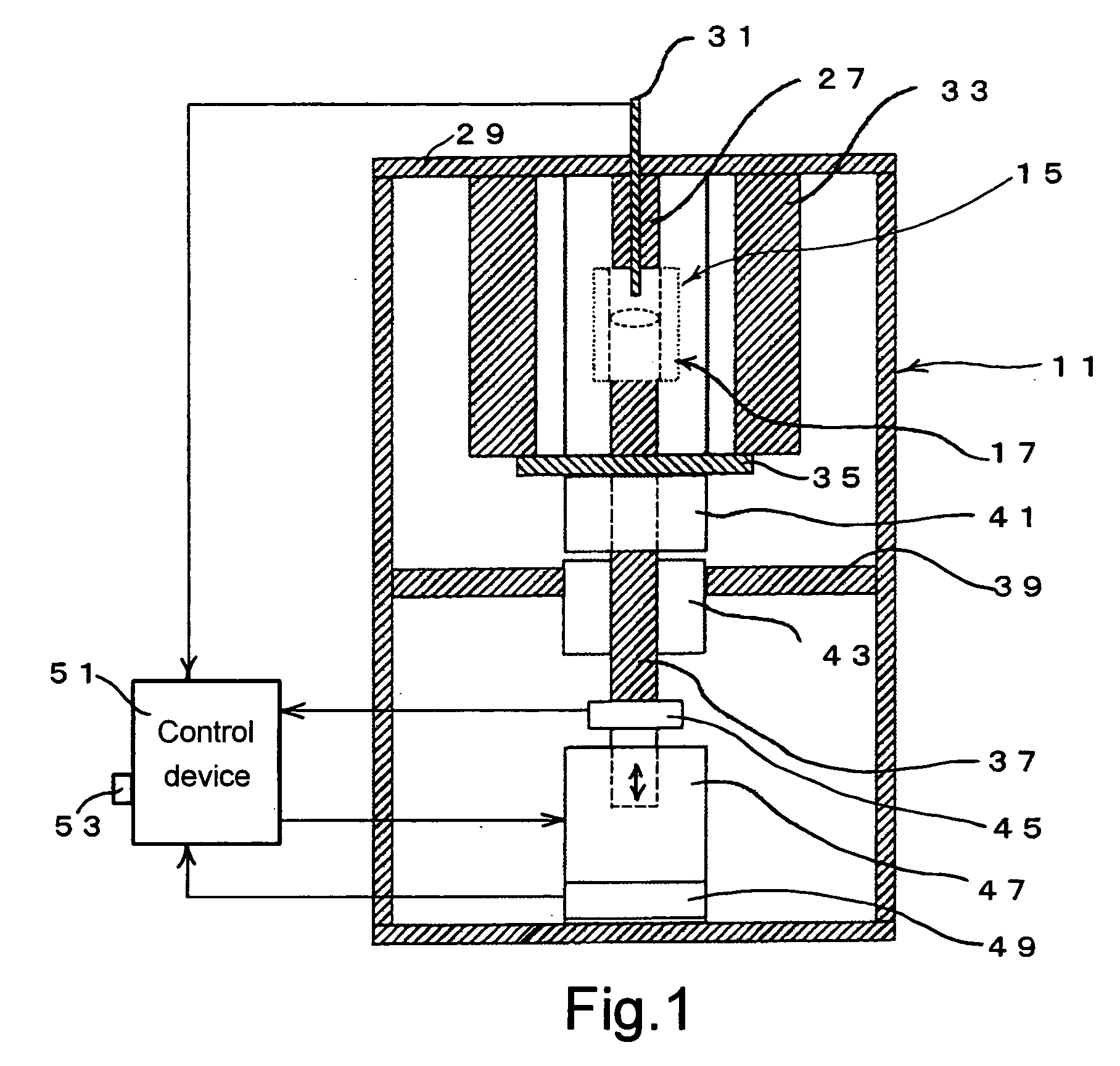
[0038]FIG. 1 shows a first embodiment of an optical element molding apparatus according to the present invention.

[0039] In this embodiment, a molding chamber 15 is provided in an upper part of an apparatus body 11. Molding is performed while a mold assembly 17 is arranged in the molding chamber 15.

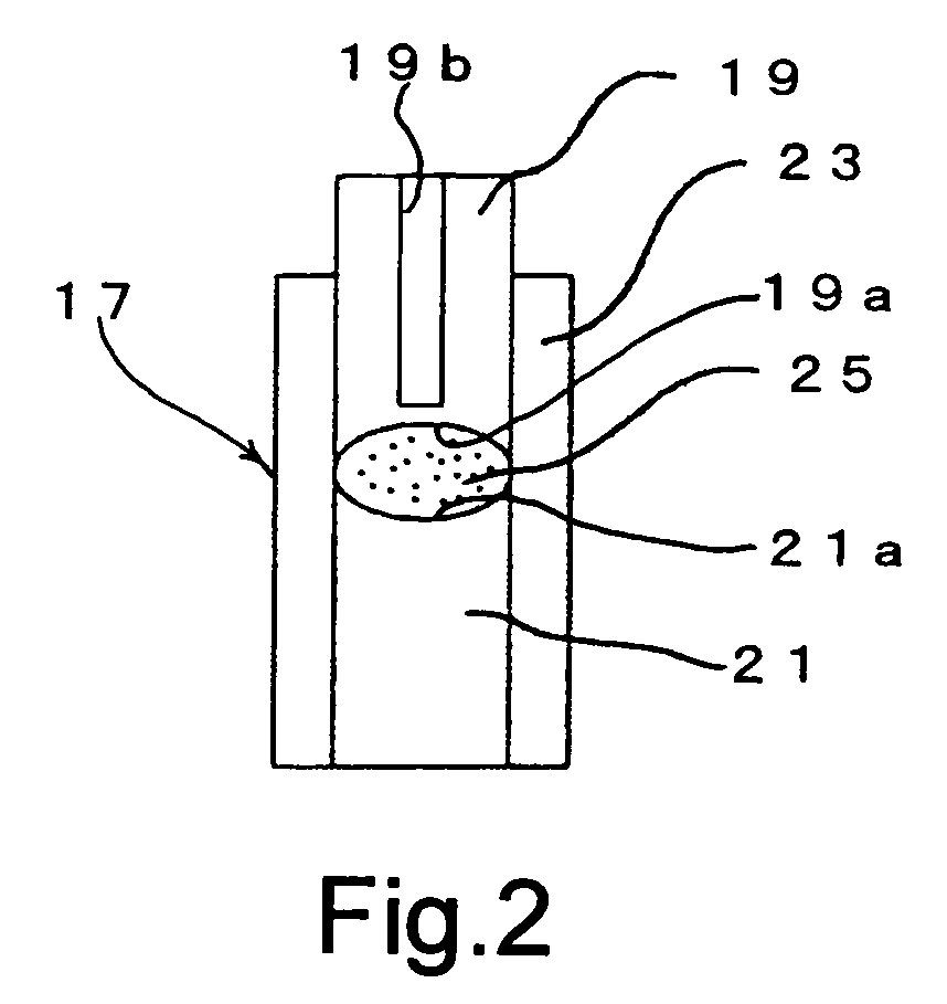
[0040]FIG. 2 shows details of the mold assembly 17. The mold assembly 17 includes an upper mold 19 and a lower mold 21. The upper mold 19 and the lower mold 21 are fitted into a cylindrical sleeve 23 so as to be freely slidable upward and downward. Concave portions 19a and 21a each having a shape corresponding to a lens to be molded are formed in a lower end face of the upper mold 19 and an upper end face of the lower mold 21, respectively. A material 25 that is formed by a glass base material is accommodated between the upper mold 19 and the lower mold 21. A thermo-couple insertion hole 19b is formed in the upper mold 19. The thermo-couple insertion hole may be formed in the lower mold ...

second embodiment

[0072] A second embodiment of the present invention is now described in detail, with reference to the drawings.

[0073]FIG. 7 shows an inner cross section of a main part of an optical element molding apparatus of the present embodiment. FIG. 8 shows a transport mechanism 108. FIG. 9 shows a mold assembly 123. FIG. 10 shows a heating mechanism. The optical element molding apparatus of the second embodiment of the present invention is described with reference to FIGS. 7, 8, 9, and 10.

[0074] In the second embodiment, an arrangement for carrying in and out the mold assembly 123 with a material accommodated therein to / from a molding chamber and an arrangement for forming an atmosphere of inert gas in a molding part are mainly described. An arrangement and a control method for moving a lower shaft 139 and the like are the same as those in the first embodiment and therefore the detailed description thereof is omitted.

[0075] In FIG. 7, the optical element molding apparatus of the present e...


PUM

PropertyMeasurementUnit
Pressureaaaaaaaaaa
Molding pressureaaaaaaaaaa

Abstract

A material for an optical element is accommodated between a first mold and a second mold, and is pressurized by relatively moving the first mold and the second mold while the material is heated to a predetermined temperature, thereby molding the optical element having a predetermined shape. This method determines, as a molding-reference distance, a distance between the first mold and the second mold of when a molding pressure which is generated between the first mold and the second mold applied to the material reaches a predetermined pressure, and moves either one of the first mold and the second mold from the molding-reference distance by a predetermined distance, thereby finishing molding of the optical element. Therefore, it is possible to reduce errors in the shapes of the final molding space easily and surely.

Description

CROSS REFERENCE TO RELATED APPLICATION [0001] This application is a continuation of PCT International Patent Application No. PCT / JP2004 / 008954, filed on Jun. 18, 2004, designating the U.S., and claims the benefit of priority from Japanese Patent Application No. 2003-186533, filed on Jun. 30, 2003, the entire contents of which are incorporated herein by reference.BACKGROUND OF THE INVENTION [0002] 1. Field of the Invention [0003] The present invention relates to an optical element molding method and an optical element molding apparatus. More particularly, the present invention relates to an optical element molding method and an optical element molding apparatus, which pressurize a material by using a mold so as to mold an optical element having a predetermined shape. [0004] 2. Description of the Related Art [0005] Conventionally a molding method is known which molds a glass element having a predetermined shape by accommodating a glass material between an upper mold and a lower mold a...

Claims


Application Information

Patent Timeline
IPC IPC(8): C03B11/16C03B11/12C03B11/00
CPCC03B11/122C03B11/16C03B2215/69
Inventor SHIBASAKI, AKIYOSHIKURIHARA, SATOSHIHORIKAWA, TADASHI
Owner NIKON CORP
Why Eureka
Try Eureka