Rapid rotating device for ratchet belt shaft

Inactive Publication Date: 2006-04-20
ASIAN IND PROD USA INC
View PDF17 Cites 8 Cited by
  • Summary
  • Abstract
  • Description
  • Claims
  • Application Information

AI Technical Summary

Benefits of technology

[0012] Compared to the current method of exerting the crowbar directly into the end of the belt shaft, the ratchets utilizing the rapid rotating device possesses benefits such as safe, reliable and effortless operation; no need to remove and re-insert the crowbar,

Problems solved by technology

It is a common practice to tie the goods down with ropes to the bed of trucks, although it may be a time consuming process that requires a lot of effort, and is difficult to secure the goods prop

Method used


Image

  • Rapid rotating device for ratchet belt shaft
  • Rapid rotating device for ratchet belt shaft
  • Rapid rotating device for ratchet belt shaft

Examples


Embodiment Construction

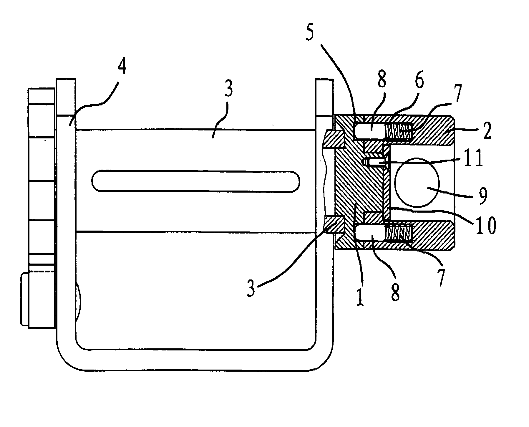
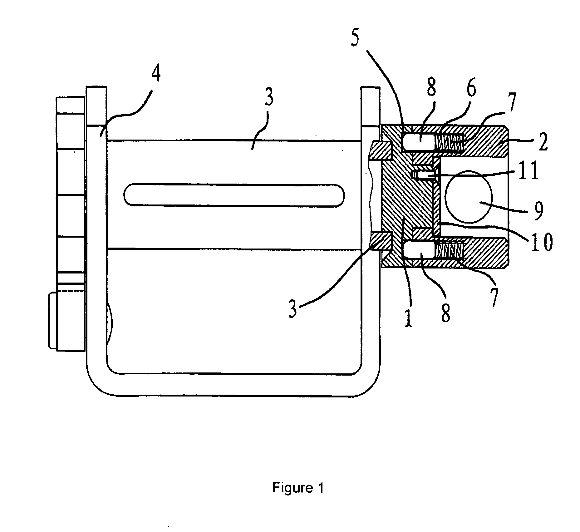
[0019] As shown in FIG. 1, the rapid rotating device is set up on the extended part of the belt shaft 3 that is on the side of the ratchet supporting frame 4. The device includes a fixed base 1 and a rotating body 2. Belt shaft 3 can be rotated, and is installed on the ratchet supporting frame 4. When in use, belt shaft 3 will be wrapped with belt. Fixed base 1 is firmly attached to belt shaft 3.

[0020] Rotating body 2 is inserted circumferentially along the side of the fixed base 1. In this example, a locating plate 10 is installed between the rotating body 2 and fixed base 1, while rotating body 2 is socketed onto the fixed base 1, and is attached onto the fixed base 1 by means of bolted down by screws 11 over locating plate 10. By adapting mechanisms as above, rotating body 2 is well attached to the fixed base 1, and can be rotated against fixed base 1.

[0021] As shown in FIG. 1, there is a crowbar hole on the rotating body 2. A side is perpendicular to the side surface of the fi...


PUM

PropertyMeasurementUnit
Forceaaaaaaaaaa
Mechanical propertiesaaaaaaaaaa
Torqueaaaaaaaaaa

Abstract

A ratchet mechanism for a cargo tie-down including a unidirectional coupling. The unidirectional coupling is adapted to receive a bi-directional torque at an input thereof, and provide a unidirectional torque to a belt shaft at an output thereof.

Description

FIELD OF THE INVENTION [0001] The present invention relates to a tie-down, and more particularly to a ratchet tie-down. BACKGROUND [0002] During the transportation of goods through automobile, the goods will need to be secured to prevent the goods from falling off the automobile, or crashing into one another to induce damage. It is a common practice to tie the goods down with ropes to the bed of trucks, although it may be a time consuming process that requires a lot of effort, and is difficult to secure the goods properly. [0003] A ratchet is an advanced tying tool. Ratchets have been well received among truck drivers due to the ease of use and safety concerns when tying down the goods. As shown in FIG. 5, there is a frame 4 and belt shaft 3 on the ratchet with belt shaft 3 located on the frame 4, and belt shaft can be turned. The tie-down belt is then wrapped around the belt shaft 3, and can be tightened when turning the belt shaft 3, and to retract the belt. [0004] The current met...

Claims


Application Information

Patent Timeline
IPC IPC(8): B25B25/00
CPCB60P7/083
Inventor RUAN, BU QIN
Owner ASIAN IND PROD USA INC
Why Eureka
Try Eureka