Rapid rotating device for ratchet belt shaft

a ratchet and belt technology, applied in the field of ratchet tiedown, can solve the problems of time-consuming process, difficult to secure goods properly, and difficulty in tying with ropes, so as to improve the speed of tying, increase the ease of use of ratchet, and ensure the effect of safety and reliability

Inactive Publication Date: 2009-07-14
ASIAN IND PROD USA INC
View PDF19 Cites 12 Cited by
  • Summary
  • Abstract
  • Description
  • Claims
  • Application Information

AI Technical Summary

Benefits of technology

[0007]The present invention resolves many of the issues mentioned above. This invention provides a rapid rotating device such that it will not be necessary to remove and insert the crowbar during operation. Thus easy, effortless operation is achieved, and tie-down speed is increased while ensuring safe and reliable operation.
[0013]Compared to the current method of inserting a crowbar directly into a bore in the end of the belt shaft, a ratchet utilizing the rapid rotating device of the invention possesses benefits such as safe, reliable and effortless operation; no need to remove and re-insert the crowbar, and won't harm the product or the operator. In the meantime, there is no restriction on the latitude of forward and backward motion on the crowbar, which increases the ease of use of the ratchet, and improves the speed of tying, resulting in higher practical value.

Problems solved by technology

This may be a time consuming process, however.
Tying with ropes requires a lot of effort, and it is difficult to secure the goods properly.
Obviously, this is a slow process, and it takes a lot of effort.
In the meantime, it is possible to cause harm to fingers or other body parts due to frequent insertions and removals of the crowbar.

Method used


Image

  • Rapid rotating device for ratchet belt shaft
  • Rapid rotating device for ratchet belt shaft
  • Rapid rotating device for ratchet belt shaft

Examples


Embodiment Construction

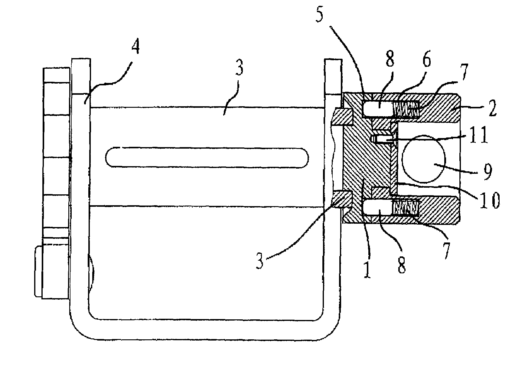
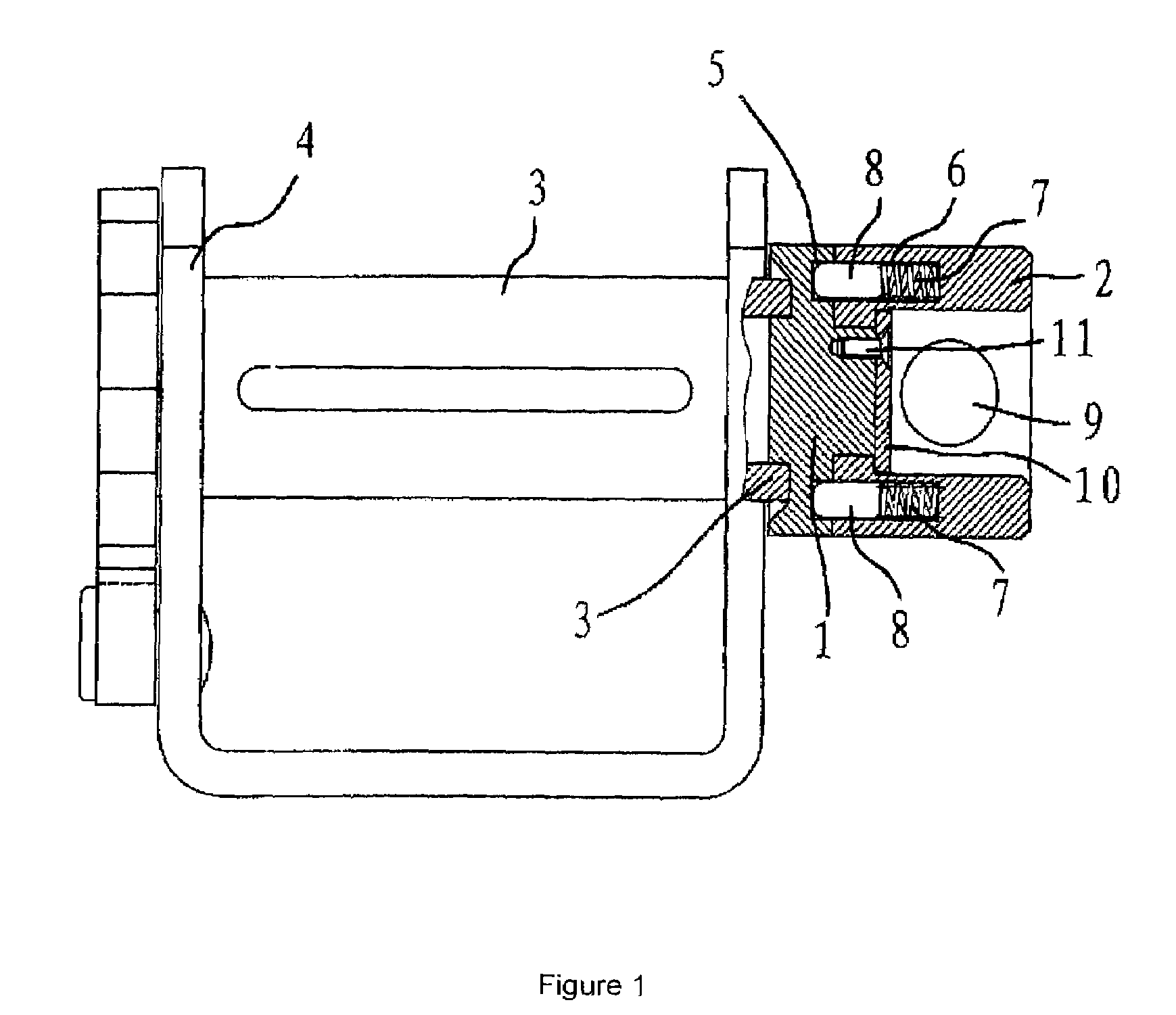
[0020]As shown in FIG. 1, the rapid rotating device is supported on the extended part of the belt shaft 3 that is disposed outwardly of the ratchet supporting frame 4. The device includes a fixed base 1 and a rotating body 2. Belt shaft 3 can be rotated, and is installed on the ratchet supporting frame 4. When in use, belt shaft 3 is wrapped with a belt. Fixed base 1 is firmly attached to belt shaft 3.

[0021]Rotating body 2 is inserted circumferentially along the side of the fixed base 1. In this example, a retaining plate 10 is installed to capture the rotating body 2 adjacent fixed base 1. Thus rotating body 2 is socketed onto the fixed base 1, and is attached onto the fixed base 1 by means of bolt-down screws 11 through locating plate 10. By adapting mechanisms as above, rotating body 2 is well attached to the fixed base 1, and can be rotated against fixed base 1.

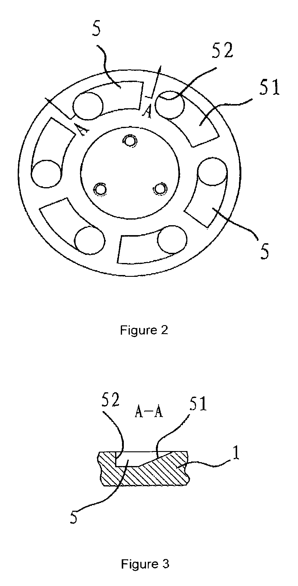
[0022]As shown in FIG. 1, rotating body 2 includes a crowbar hole. A straight side 52 is perpendicular to the side surf...


PUM

PropertyMeasurementUnit
timeaaaaaaaaaa
angleaaaaaaaaaa
spring forceaaaaaaaaaa

Abstract

A ratchet mechanism for a cargo tie-down includes a unidirectional coupling. The unidirectional coupling is adapted to receive a bidirectional torque at an input thereof, and provide a unidirectional torque to a belt shaft at an output thereof.

Description

CROSS-REFERENCE TO RELATED APPLICATIONS[0001]The present application claims priority to Chinese patent application numbers 200410052805-7 and 200420037526-9, both filed Jul. 14, 2004, the disclosures of which are herewith incorporated by reference in their entirety.FIELD OF THE INVENTION[0002]The present invention relates to a tie-down, and more particularly to a ratchet tie-down.BACKGROUND[0003]When goods are transported by automobile, the goods need to be secured to prevent the goods from falling off the automobile, or colliding with one another to induce damage. It is a common practice to tie goods down to the bed of a truck with ropes. This may be a time consuming process, however. Tying with ropes requires a lot of effort, and it is difficult to secure the goods properly.[0004]A ratchet is an advanced tying tool. Ratchets have been well received among truck drivers due to their ease of use and to safety concerns when otherwise tying down the goods. As shown in FIG. 5, there is ...

Claims


Application Information

Patent Timeline
Patent Type & Authority Patents(United States)
IPC IPC(8): B60P7/08
CPCB61D45/00B60P7/083
Inventor RUAN, BU QIN
Owner ASIAN IND PROD USA INC
Why Eureka
Try Eureka