
Cassette of cassette type stapler

Inactive Publication Date: 2006-04-27
E TOP CORP
View PDF15 Cites 0 Cited by
  • Summary
  • Abstract
  • Description
  • Claims
  • Application Information

AI Technical Summary

Benefits of technology

[0083] According to this invention, an integrally molded holder structure for use in the cassette of the cassette type stapler can be provided by a set of molds. The holder structure is obtained by once parting the molds so that the cost and the labors of manufacture can be remarkably lowered.
[0084] At the time of using the holder member, moreover, no trouble occurs, as might otherwise be caused due to removal of glue or screws.
[0085] The cassette according to this invention is completed by the four parts of the holder structure, the feeder, the spring and the staples so that it can be manufactured with less parts and at a remarkably low cost. Moreover, the labors are drastically reduced for the manufacture.
[0086] In case the cassette of this invention adopts the mechanism in which the staples are guided by the engagement of their top backs, the

Problems solved by technology

In the course of the mass production, however, many labors are required for fitting the engaging projection of the rod structure in the hole

Method used


Image

  • Cassette of cassette type stapler
  • Cassette of cassette type stapler
  • Cassette of cassette type stapler

Examples


Example

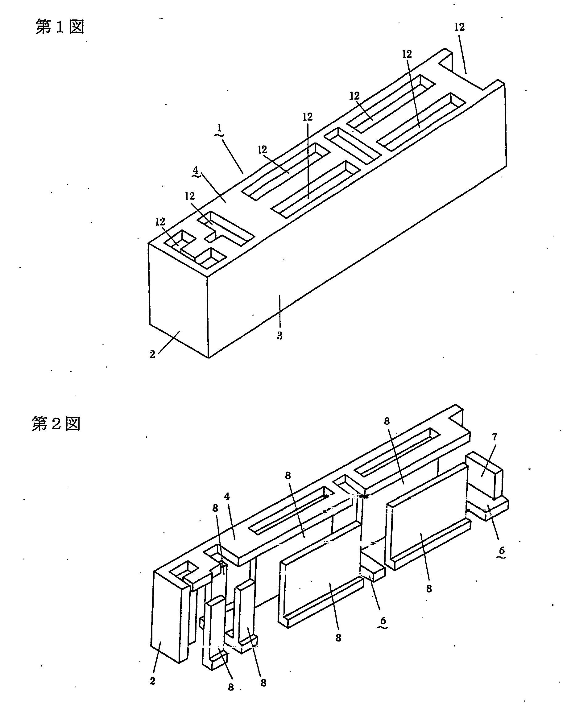
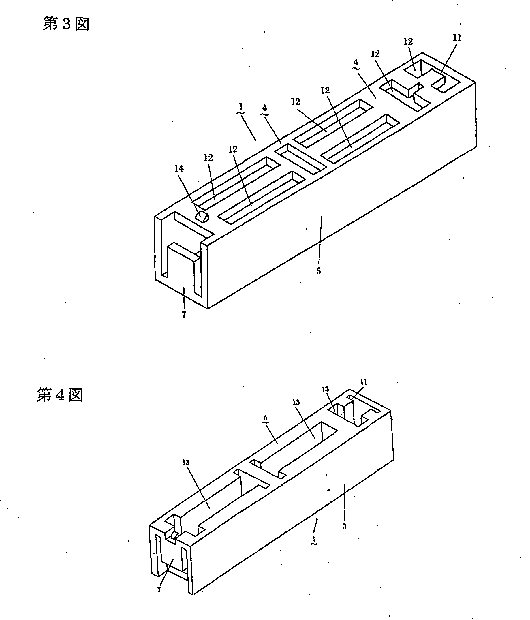
[0154]1—Holder Structure, 2—Holder Front Side, 3—Holder Right Side, 4—Holder Top Side, 5—Holder Left Side, 6—Holder Bottom Side, 7—Holder Back Side, 8—Staple Guide, 9—Spring Engaging Member, 10—Engaging Projection, 11—Feeder Hole, 12—Recess, 13—Recess, 14—Stapler Engaging Projection, 15—Staple, 16—Beam, 17—Recess, 20—Feeder, 21—Feeder Projection, 22—Spring, 25—Staple, 26—Beam, 27—Spring Guide, 28—Staple Guide, 29—Spring Engaging Member, 30—Feeder, 31—Feeder Projection, 32—Spring, 34—Spring Guide, 35—Staple Guide, 36—Spring Engaging Member, 40—Staple, 41—Beam, 42—Side Wall Staple Guide, 43—Spring Engaging Member, 44—Feeder, 45—Feeder Projection, 46—Spring, 50—Staple, 51—Spring Guide, 52—Side Wall Staple Guide, 53—Spring Engaging Member, 54—Small Projection, 55—Feeder, 56—Feeder Projection, 57—Spring, 60—Staple, 62—Side Wall Staple Guide, 63—Spring Engaging Member, 65—Feeder, 66—Feeder Spring Engaging Portion, 80—Cassette, 81—Holder Member, 83—Feeder Device, 84—Staple, 85—Spring, 86—R...


PUM


Abstract

A cassette of a cassette type stapler, wherein a holder structural body (1), staple guides (8), and a spring engaging device (9) of the holder structural body are molded integrally with each other, a spring is fitted to the spring engaging device (9) of the holder structural body and the feeder projection (21) of a feeder (20), and the feeder (20) pushes a staple forward. Namely, a mechanism functioning as a conventional outer box is formed integrally with a mechanism guiding the staple. Also, in the mechanism functioning as the outer box, a rear wall or a bottom wall is not separated from the outer box but formed integrally therewith. In addition, a structure to directly engage one end of the spring with a holder body and the other end with the feeder and a structure to guide the staple to a specified position when the staple is struck out are used for the mechanism guiding the staple. A member for engaging the spring with the holder body and a staple guide member are required for these structures. These structures are also formed integrally with a holder.

Description

TECHNICAL FIELD THE INVENTION BELONGS TO [0001] The present invention relates to a cassette to be used in a cassette type stapler and to a holder structure to be used in said cassette. PRIOR ART [0002] As the cassette for the cassette type stapler of the prior art, there are a cassette disclosed in JP-A-62-218080 and a cassette disclosed in JP-A-63-47076. A cassette 80 (FIG. 59 to FIG. 61) disclosed in JP-A-62-218080 widely spreads in the market. Not only a holder member 81 but also a feeder device 82 and a rod structure 86 (FIG. 60) are essential in the cassette 80. The holder member 81 is formed into a box shape having its back wall removed, and a cap 87 of the rod structure 86 functions as the back wall of the holder member. Specifically, the assembly of the cassette 80 is completed by mounting staples 84 and the feeder device 82 in the recited order from the back of the holder member 81, by mounting a rod 88 of the rod structure 86 having a spring 85 attached thereto, and by int...

Claims


Application Information

Patent Timeline
IPC IPC(8): B25C5/06B25C5/16
CPCB25C5/161B25C5/1637B25C5/1658B25C5/1686
Inventor EBIHARA, YOSHIYUKI
Owner E TOP CORP
Learn More