
Method and apparatus for effectively encoding multi-layered motion vectors

a multi-layered motion vector and motion vector technology, applied in the field of video compression, can solve the problems of difficult task of efficiently redundancy between motion vectors, high effort is being made to implement scalability based on multi-layered structure, etc., and achieve the effect of efficient encoding multi-layered motion vectors

Inactive Publication Date: 2006-04-27
SAMSUNG ELECTRONICS CO LTD
View PDF9 Cites 70 Cited by
  • Summary
  • Abstract
  • Description
  • Claims
  • Application Information

AI Technical Summary

Benefits of technology

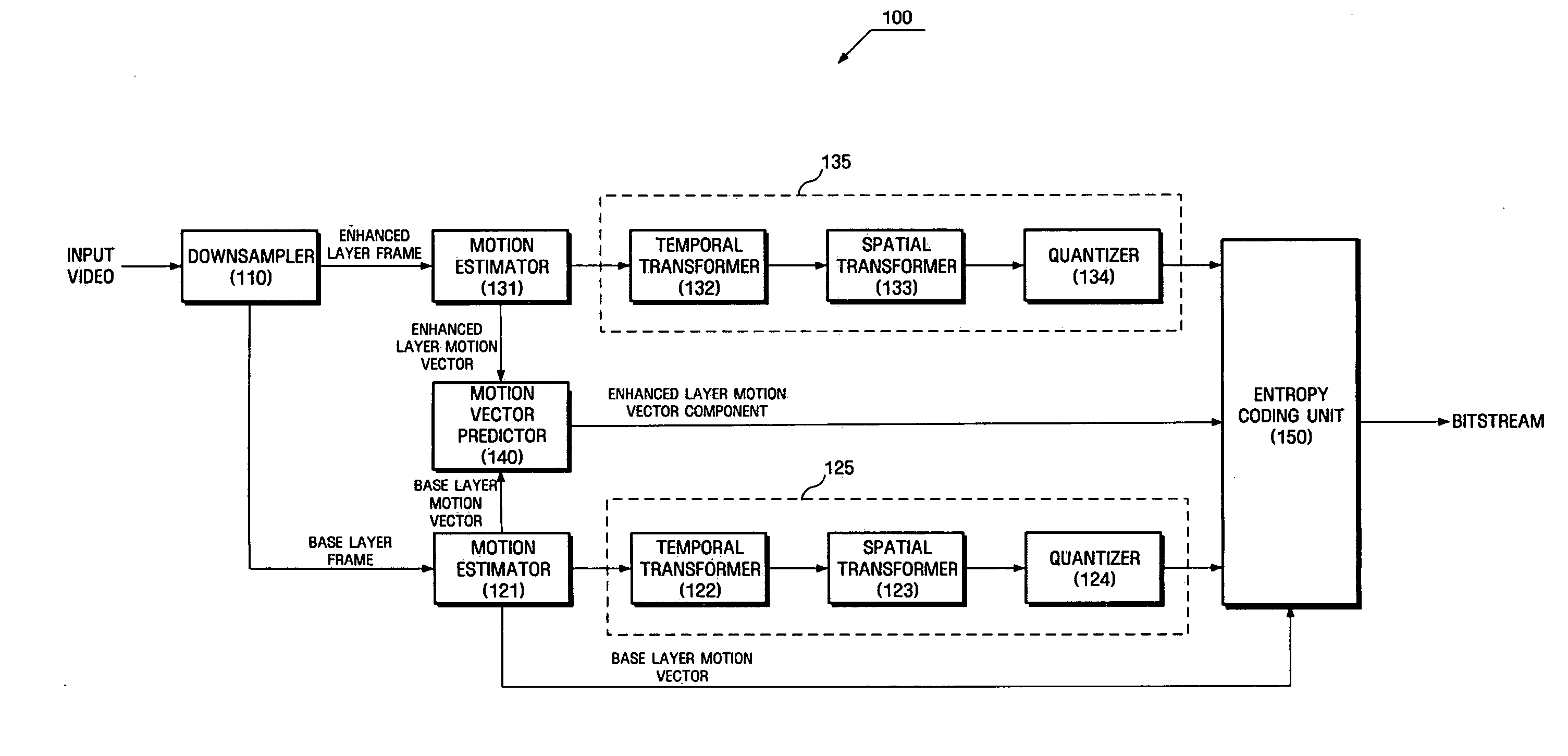
[0016] The present invention provides an apparatus and method for efficiently predicting a motion vector in an enhanced layer from a motion vector in a base layer.
[0018] According to an aspect of the present invention, there is provided a method for efficiently encoding multi-layered motion vectors, including: obtaining a motion vector in a mother frame of a base layer that is temporally closest to an unsynchronized frame of a current layer; obtaining a predicted motion vector from the motion vector in the mother frame considering the referencing direction in the mother frame and in the unsynchronized frame and distances between the mother frame and a reference frame and between the unsynchronized frame and a reference frame; generating a residual between the motion vector in the unsynchronized frame and the predicted motion vector; and encoding the motion vector in the mother frame and the residual.

Problems solved by technology

However, multimedia data requires a storage media that have a large capacity and a wide bandwidth for transmission since the amount of multimedia data is usually large.
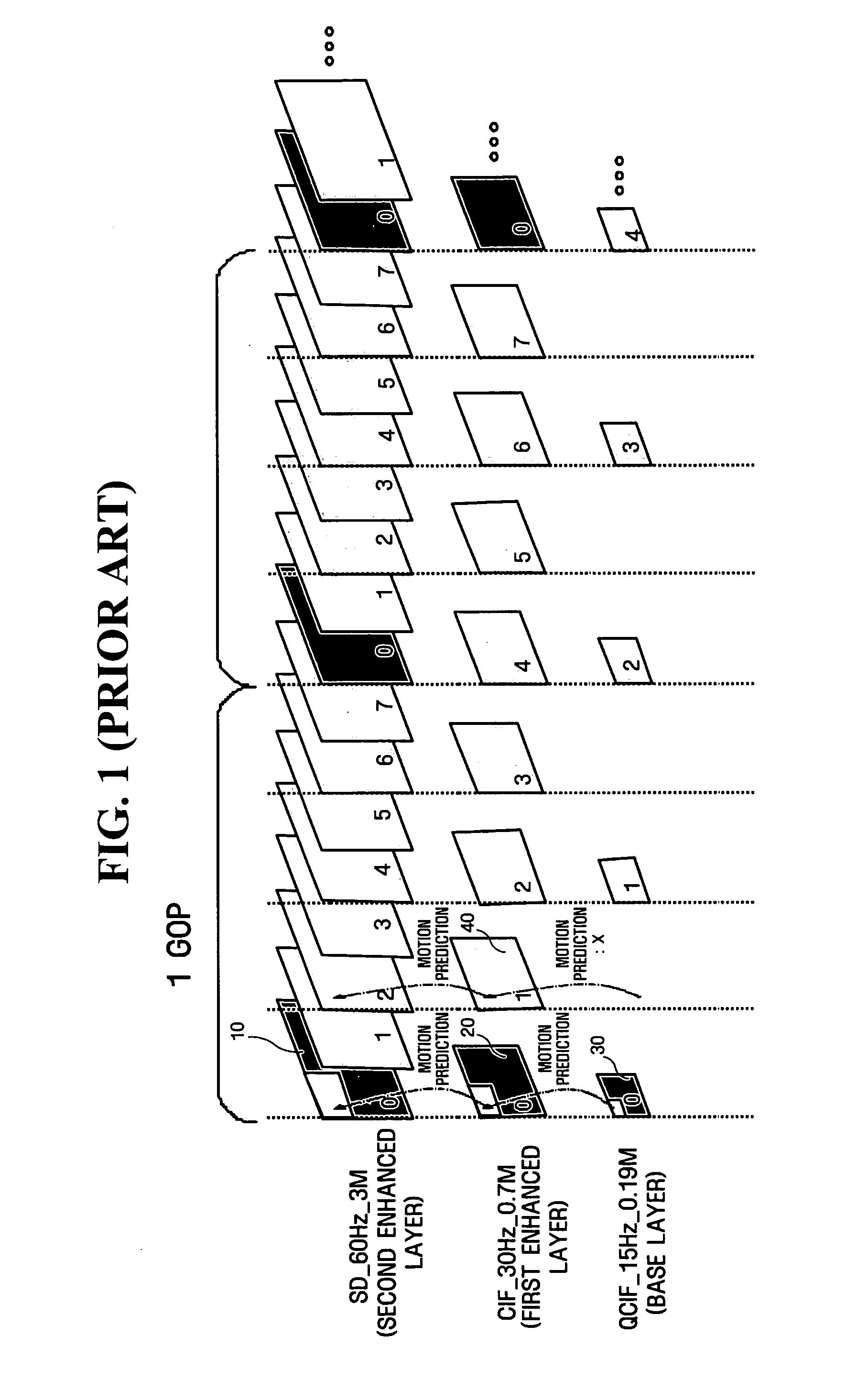
In particular, much effort is being made to implement scalability based on a multi-layered structure.
Thus, it is a very challenging task to efficiently redundancy between motion vectors for each layer.

Method used


Image

  • Method and apparatus for effectively encoding multi-layered motion vectors
  • Method and apparatus for effectively encoding multi-layered motion vectors
  • Method and apparatus for effectively encoding multi-layered motion vectors

Examples


first exemplary embodiment

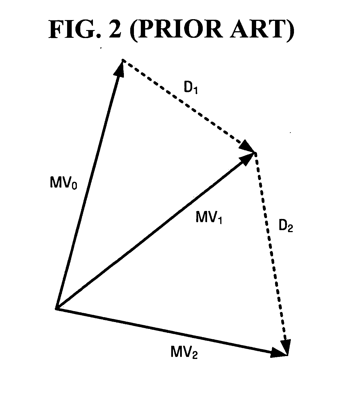
[0054] A virtual motion vector is used as a motion vector in an unsynchronized frame of a current layer. When a motion vector in the unsynchronized frame has the same direction as a motion vector in a mother frame as shown in the Equations (1) through (3), the virtual motion vector is obtained by multiplying the motion vector in the mother frame by the ratio of temporal referencing distance between layers (e.g., ½). When the motion vector in the unsynchronized frame has an opposite direction to the motion vector in the mother frame, the virtual motion vector is obtained by multiplying the power by −1.

[0055] Furthermore, since sub-macroblock patterns in an unsynchronized high-pass virtual frame of the current layer are the same as those in the mother frame, a motion vector in the unsynchronized frame is predicted using sub-macroblock patterns in the mother frame. Thus, motion vector search and R-D optimization for selecting a sub-macroblock pattern are not performed for the unsynchr...

second exemplary embodiment

[0056] In the second exemplary embodiment, sub-macroblock patterns in an unsynchronized frame and a mother frame are determined by a separate R-D optimization process. While a virtual motion vector is derived from the mother frame after completing the R-D optimization, the sub-macroblock patterns in the mother frame are different from those in the unsynchronized frame. When the sub-macroblock patterns are different, a motion vector from a sub-macroblock in the unsynchronized frame can be induced from a virtual motion vector overlapped by the sub-macroblock pattern in the unsynchronized frame. To achieve this, the present invention uses the weighted average of the areas of overlapped regions.

[0057]FIG. 6 shows an example in which a sub-macroblock pattern in a mother frame corresponding to a sub-macroblock in an unsynchronized frame is further divided into sections. Here, Mvi and Ai respectively denote a virtual motion vector obtained as defined by the Equations (1) through (3) and t...

third exemplary embodiment

[0059] The third exemplary embodiment focuses on each pixel of a virtual frame. First, a check is made as to all motion vectors passing through a pixel of the virtual frame. A virtual base motion vector for one pixel (“pixel motion vector”) is estimated by a distance-weighted average (distance between centers of the pixel and sub-macroblock). Various distance measures such as Euclidean distance or City Block distance may be used for distance estimation.

[0060] A sub-macroblock pattern in an unsynchronized frame is decided by an R-D optimization process. When a motion vector in the unsynchronized frame is replaced by a virtual motion vector, virtual base motion vectors for the sub-macroblock are estimated using all pixel motion vectors within the same sub-macroblock in the virtual frame. FIG. 8 illustrates a method for estimating virtual base motion vectors.

[0061] A motion vector for a pixel of interest 50 in a virtual frame is derived from motion vectors passing through the pixel. ...


PUM


Abstract

An apparatus and method for improving the compression efficiency of a motion vector by efficiently predicting a motion vector in an enhanced layer from a motion vector in a base layer in a video coding method using a multi-layer structure are provided. The method includes obtaining a motion vector in a mother frame of a base layer that is temporally closest to an unsynchronized frame of a current layer, obtaining a predicted motion vector from the motion vector in the mother frame considering the referencing direction in the mother frame and in the unsynchronized frame and distances between the mother frame and a reference frame and between the unsynchronized frame and a reference frame, generating a residual between the motion vector in the unsynchronized frame and the predicted motion vector, and encoding the motion vector in the mother frame and the residual.

Description

CROSS-REFERENCE TO RELATED APPLICATION [0001] This application claims priority from Korean Patent Application Nos. 10-2004-0103059 and 10-2005-0016269, filed on Dec. 8, 2004 and Feb. 26, 2005, respectively, and U.S. Provisional Patent Application Nos. 60 / 620,328, 60 / 641,750 and 60 / 643,127, filed on Oct. 21, 2004, Jan. 7, 2005 and Jan. 12, 2005, respectively, the whole disclosures of which are hereby incorporated herein by reference.BACKGROUND OF THE INVENTION [0002] 1. Field of the Invention [0003] Apparatuses and methods consistent with the present invention relate to video compression, and more particularly, to improving the compression efficiency of a motion vector by efficiently predicting a motion vector in an enhanced layer from a motion vector in a base layer in a video coding method using a multi-layer structure. [0004] 2. Description of the Related Art [0005] With the development of information communication technology, including the Internet, video communication as well as...

Claims


Application Information

Patent Timeline
IPC IPC(8): H04N11/02H04N7/12H04N11/04H04B1/66
CPCH04N5/145H04N19/52H04N19/139H04N19/51H04N19/102H04N19/61H04N19/649H04N19/62H04N19/33H04N19/31H04N19/59H04N19/577H04N19/187B43L9/02B43L9/24
Inventor LEE, KYO-HYUKCHA, SANG-CHANGHAN, WOO-JIN
Owner SAMSUNG ELECTRONICS CO LTD
Learn More