Moving pictures encoding method and apparatus for detecting a scene change between fields of an interlaced image

a technology of interlaced images and encoding methods, applied in the field of moving pictures encoding methods, can solve the problems of increasing the amount of coded data, unable to say good efficiency, and the amount of information comprising the moving picture itself, and achieve good picture quality encoding

Inactive Publication Date: 2008-11-18
FUJITSU LTD
View PDF9 Cites 54 Cited by
  • Summary
  • Abstract
  • Description
  • Claims
  • Application Information

AI Technical Summary

Benefits of technology

[0044]Therefore, an object of the present invention is to provide a moving pictures encoding method and apparatus, which are capable of achieving encoding effi

Problems solved by technology

In general, the amount of information comprising a moving picture itself is huge.
However, efficiency cannot be said to be good if encoding is performed using only a P-picture or a B-picture, which have small amounts of data.
Here, when an I-picture is put to multiple uses, it is undesirable because the same scene is coded at the same picture quality, thereby increasing the amount of coded data.
When encoding is performed at a fixed rate, picture unit data allocation becomes that much smaller, and picture quality deteriorates.
However, when scene changes and other inter-picture correlation is low, prediction efficiency deteriorates when inter-picture prediction is used, and in some cases, picture quality deteriorates even more than when intra-picture encoding is performed.
When all is said and done, this method is undesirable because an I-picture, or an intra-picture coded picture is generated each time a scene change occurs, increasing the volume of coded data by that much.
However, in the case of the example shown in FIG. 30, if it is assumed that the encoding process is achieved in real-time using

Method used


Image

  • Moving pictures encoding method and apparatus for detecting a scene change between fields of an interlaced image
  • Moving pictures encoding method and apparatus for detecting a scene change between fields of an interlaced image
  • Moving pictures encoding method and apparatus for detecting a scene change between fields of an interlaced image

Examples


first embodiment

[0124]FIG. 9 is a block diagram of an example of a constitution of a motion prediction decision device 6, which, as the present invention, realizes the above-mentioned first solution principle of the present invention. The present invention is characterized by the fact that it provides yet another prediction comparator 64 relative to the constitution of the motion prediction decision device 6 of FIG. 8.

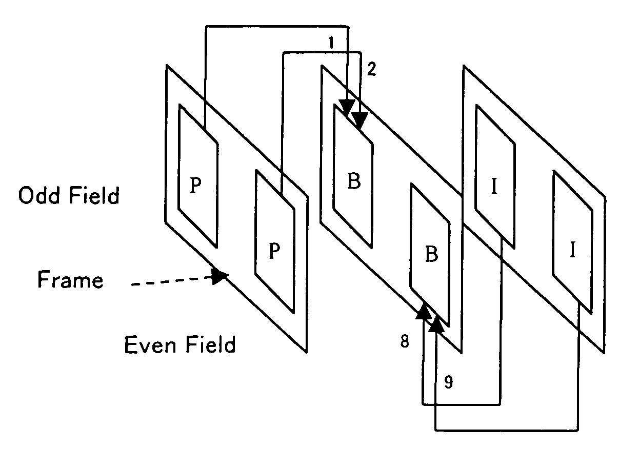
[0125]Frame structure encoding realized by the embodiment shown in FIG. 9, as the first solution principle of the present invention illustrated in FIG. 1, adds a predictive mode, which, in B-picture field prediction, performs prediction from the forward direction for one field, and prediction from the backward direction for the other field.

[0126]To add this predictive mode, there is a possibility that an additional bit will be required in a macro-block unit from the standpoint of the syntax (data string convention). Therefore, this predictive mode is advantageous in that the constitut...

second embodiment

[0132]FIG. 10 is a block diagram of an example of a constitution of a motion prediction decision device 6 according to yet the present invention. The constitution is such that the output of prediction comparator 64, which is added relative to the embodiment of FIG. 9, is constantly inputted to prediction comparator 63.

[0133]Therefore, the constitution is such that, for a B-picture, prediction, which is always from a forward field prediction result for one field, and from a backward field prediction result for the other field, is entered into an item.

[0134]As described above, according to the present invention, a prediction mode, wherein there is 1 motion vector per direction in field prediction, is added as a new prediction mode.

[0135]Table 4 is a code table for an MPEG-2 frame structure prediction mode (Table 6-17 Meaning of frame#motion#type: ISO / IEC 13818-2 (MPEG-2-Video) definition of frame#motion#type).

[0136]

TABLE 4SpatialTemporalMotionWeightPredictionvectorMvCodeClassTypeCount...

third embodiment

[0146]FIG. 12 is a diagram illustrating the present invention. The constitution of FIG. 12 is such that, relative to the constitution of FIG. 9, the switching of the switch SW is controlled by a field scene change detecting circuit 65.

[0147]Now, in relation to the above description of the second embodiment, the ‘00’ of the code column in the above Table 3 becomes a ‘reserved’ bit in order to make the MPEG start code, which commonly holds a 0 in bit 23 and a 1 in bit 1, a unique word.

[0148]Therefore, when it is impossible to allocate a new motion prediction type to ‘00’, either the bits of a frame#motion#type must be increased 1 bit, or a new, at the minimum 1-bit mode identification bit must be provided.

[0149]In this case, since motion prediction is performed in macro-block units, for example, even if an additional bit is 1 bit, when conversion is carried out per picture, it constitutes a huge increase in bit quantity. Furthermore, it is very possible that efficiency is raised in ac...


PUM


Abstract

An encoding method, which achieves encoding efficiency, and good picture quality encoding even when there exists a picture in which a scene change occurs within an interlaced frame, is provided. A moving pictures encoding method treats a frame of interlaced image input signals as a picture, and performs prediction and encoding for this picture in macro-block units from a picture of both a forward picture, which is temporally in the past, and a backward picture, which is in the future. When performing encoding in accordance with the above-mentioned bi-directional picture, the method performs inter-field motion prediction, which treats as a unit a field, which divides each picture in macro-blocks into either odd numbers or even numbers of pixel scanning lines of this frame, and as a prediction mode, selectively switches in picture units between using prediction from a forward field motion vector for one field, and using prediction from a backward field motion vector for the other field, generates a predictive picture corresponding to the selected prediction mode, and encodes the input signal using the generated predictive picture.

Description

BACKGROUND OF THE INVENTION[0001]1. Field of the Invention[0002]The present invention is related to a moving pictures encoding method, and an apparatus that uses same, which are applied to digital picture systems and applications, and picture databases utilized in a variety of fields, such as communications, broadcasting, data storage, and computers, and more particularly to a moving pictures encoding method, and an apparatus that uses same, which are advantageous when encoding picture data containing a scene change.[0003]2. Description of the Related Art[0004]In general, the amount of information comprising a moving picture itself is huge. For this reason, when encoding moving pictures, redundancy along a spatial axis is removed by using an orthogonal transform (discrete cosine transform) process and variable-length encoding. In addition, redundancy along a time axis is removed by finding the difference between the first and last frames, and encoding the difference data.[0005]The c...

Claims


Application Information

Patent Timeline
IPC IPC(8): H04N7/12H04N19/103H04N19/50H04N19/107H04N19/114H04N19/139H04N19/142H04N19/172H04N19/196H04N19/503H04N19/51H04N19/577H04N19/583H04N19/87
CPCH04N19/105H04N19/176H04N19/142H04N19/577H04N19/179H04N19/87H04N19/16
Inventor YAMORI, AKIHIROHAMANO, TAKASHISAKAI, KIYOSHIYAMADA, KOUJI
Owner FUJITSU LTD
Why Eureka
Try Eureka