Powerboat with disappearing tunnel

Inactive Publication Date: 2006-05-04
BROWN RALPH
View PDF6 Cites 0 Cited by
  • Summary
  • Abstract
  • Description
  • Claims
  • Application Information

AI Technical Summary

Benefits of technology

[0011] The invention is directed to a powerboat configuration, which overcomes the problems of the prior art. More particularly, the techniques of the invention provide for a tunnel portion, which can be utilized, in one position, to allow a propeller and drive shaft of a boat propulsion system to be protected from obstacles, debris and large mammals, which is particularly suitable for use in shallow water. In the other position, the flap closes the tunnel so that the tunnel is not active and concurrently, the positioning of the propulsion mechanism is changed to allow the propulsion unit to drop below the bottom of the hull. In this configuration, the propulsion unit is not as protected, but considerably less drag is encountered.

Problems solved by technology

A number of problems exist with respect to powerboats of the prior art.
First, they often experience difficulty when running in very shallow water.
Another problem comes from obstacles such as crab pots.
The cable that connects the floater with the crab pot can become entangled in the propeller causing the engine to stop and causing the boat operator great difficulty freeing the propeller from the cable.
A similar problem comes from encountering floating debris on the surface of the water.
Often, debris floats in such a way that it is not easily visible from the boat.
When a powerboat passes over such debris, such as a floating log, the debris may impact the propeller and bend it, or sheer the drive pin, or damage the gear mechanisms.
Serious problems exist in certain waters caused by the presence of large, slow moving mammals such as manatees.
The survival of the manatees is and has been threatened by increased boating traffic.
The manatees are often found near the surface and cannot move quickly enough to avoid powerboats, resulting in propeller cuts and other injuries to the mammals.

Method used


Image

  • Powerboat with disappearing tunnel
  • Powerboat with disappearing tunnel
  • Powerboat with disappearing tunnel

Examples


Embodiment Construction

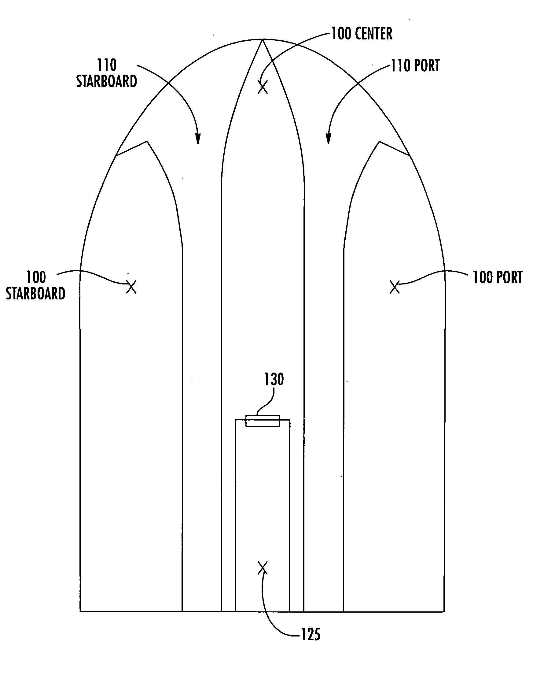
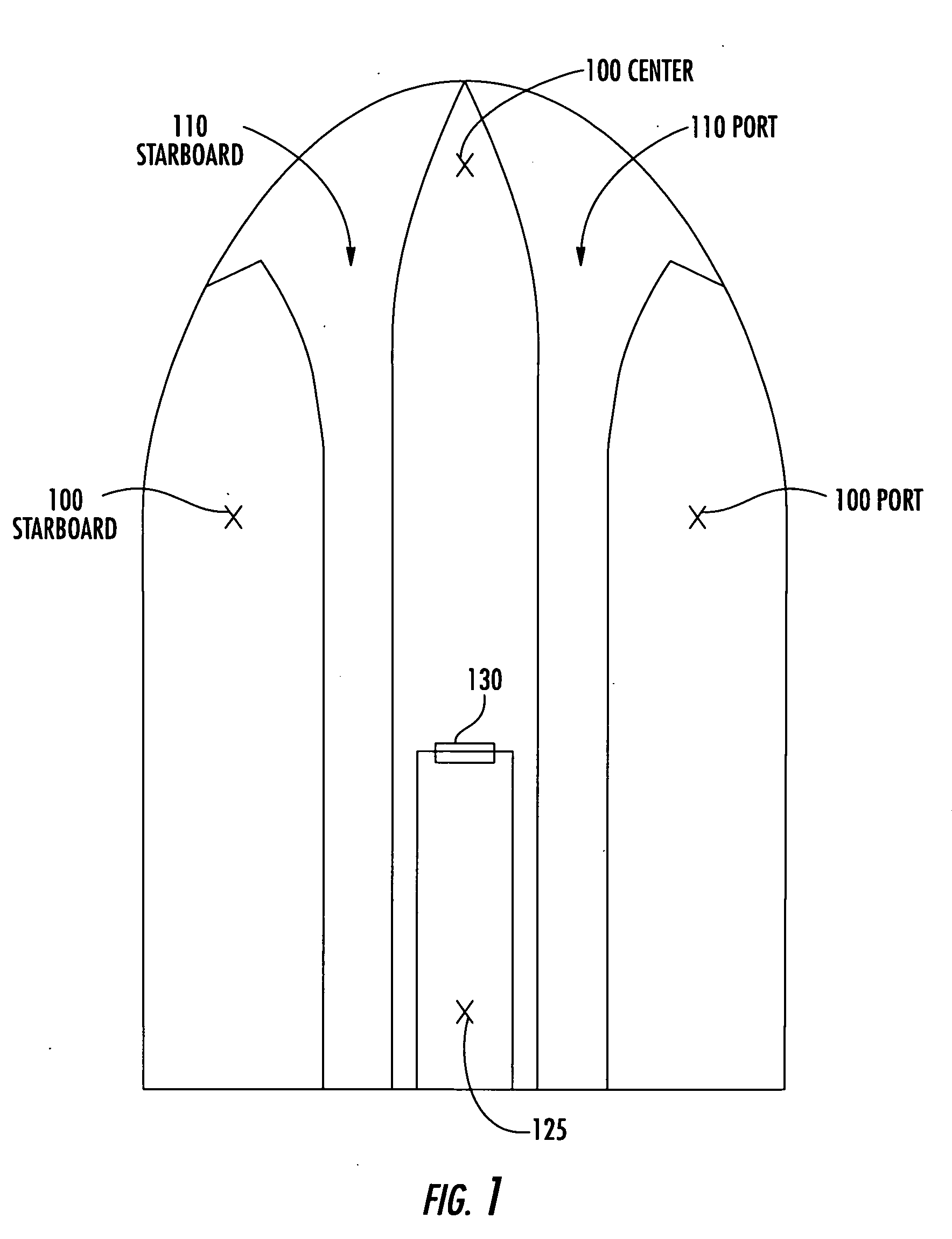
[0021]FIG. 1 is a bottom view of a hull of a boat in accordance with one aspect of the invention. In this view, one can see a moveable flap 125 that can be rotated about the axis of a hinge 130 to move from a position that is substantially flat with the bottom of the boat (i.e. one in which the tunnel underneath the flap is substantially not visible and is not functionally usable) to a second position, as described more in conjunction with FIGS. 4A and 4B.

[0022] The preferred hull configuration for use with the disappearing tunnel in accordance with the invention is the hull configuration described in U.S. patent application Ser. No. 10 / 889,624, to inventor Ralph Brown (attorney docket number 83061) filed concurrently with the parent application. The contents of application Ser. No. 10 / 889,624, are hereby incorporated herein by reference in its entirety. Alternative preferred hulls are a V-bottom hull and a flat bottom hull.

[0023]FIG. 1 is a bottom view of the hull of a boat in ac...


PUM


Abstract

A shallow draft boat has a hull that protects a propulsion propeller within a tunnel that passes only partially through the hull from stern to bow. The hull has a mechanism, such as a flap for selectively permitting or blocking water flow access to the tunnel from under the boat. The boat also has a lift mechanism preferably in the shape or adjustable parallelogram for selectively positioning a propeller of a propulsion unit substantially directly behind the tunnel or below the tunnel. The boat can operate in two modes. In one, water access to the tunnel is permitted and the propeller is positioned above the bottom of the hull and behind the tunnel. In the other, water access to the tunnel is blocked and the propelles is positioned below the bottom of the hull. This construction permits selective operation in a shallow draft mode, in a normal draft mode or in between. In the shallow draft mode, the boat prevents propulsion unit malfunction by keeping obstacles, such as debris, crab pots and mammals such as manatees from contact with the propeller.

Description

CROSS REFERENCE TO RELATED APPLICATIONS [0001] This application is a continuation in part of U.S. patent application Ser. No. 10 / 889,638, filed Jul. 12, 2004, entitled Powerboat with Disappearing Tunnel by inventor Ralph Brown, which is hereby incorporated by reference in its entirety. [0002] This application also incorporates by reference in its entirety and claims priority to U.S. Provisional Application 60 / 567,966, filed May 3, 2004, entitled Disappearing Tunnel by inventor Ralph Brown.BACKGROUND OF THE INVENTION [0003] 1. Field of the Invention [0004] The invention is directed to a powerboat configuration, and, more particularly, to a powerboat hull with a disappearing tunnel. [0005] 2. Description of Related Art [0006] A wide variety of boat constructions are well known in the art. For example, catamaran and trimaran sailboats are well known. Similarly, a significant number of powerboat constructions are well known in the art. [0007] A number of problems exist with respect to p...

Claims


Application Information

Patent Timeline
IPC IPC(8): B63B1/32B63B1/12B63B1/16B63B1/28B63H5/16
CPCB63B1/125B63B1/16B63B1/286B63H5/16
Inventor BROWN, RALPH
Owner BROWN RALPH
Why Eureka
Try Eureka