Tennis ball retriever

a tennis ball and retriever technology, applied in the field of tennis ball retriever, can solve the problems of awkward appearance, device may interfere with play, and the difficulty of picking up a tennis ball from the playing surface, and achieve the effect of convenient removal or addition, performance and appearance advantages, and convenient affixed to strings

Inactive Publication Date: 2006-05-04
BLADES FREDERICK K
View PDF14 Cites 12 Cited by
  • Summary
  • Abstract
  • Description
  • Claims
  • Application Information

AI Technical Summary

Benefits of technology

[0010] The first embodiment is an “add-on” Scoop that comprises an initially straight spring wire with resilient mounts on each end, the resilient mounts adapted to be readily affixed to the strings of a tennis racquet. During installation the spring wire is flexed into an approximately parabolic shape which is used to scoop up the tennis ball. This add-on embodiment has the advantage that no modifications to the racquet are necessary and the product can therefore be marketed and sold as an “add-on” racquet accessory.
[0011] The second and third embodiments of the present invention are “built-in” versions, so-called because they require some modification to be “built-in” to the racquet frame. Each of these two embodiments makes use of receptacles permanently installed on the racquet frame and adapted to receive and support the two ends of an initially straight spring wire adapted

Problems solved by technology

The challenge of picking up a tennis ball from the playing surface is not a great one.
However, because the former method is awkward and the latter method difficult, it is not uncommon for players to simply stoop over to pick up the ball, which can be a nuisance over the course of a long playing session.
While this prevents the player from having to stoop down to pick up the ball, the device may interfere

Method used


Image

  • Tennis ball retriever
  • Tennis ball retriever
  • Tennis ball retriever

Examples


first embodiment

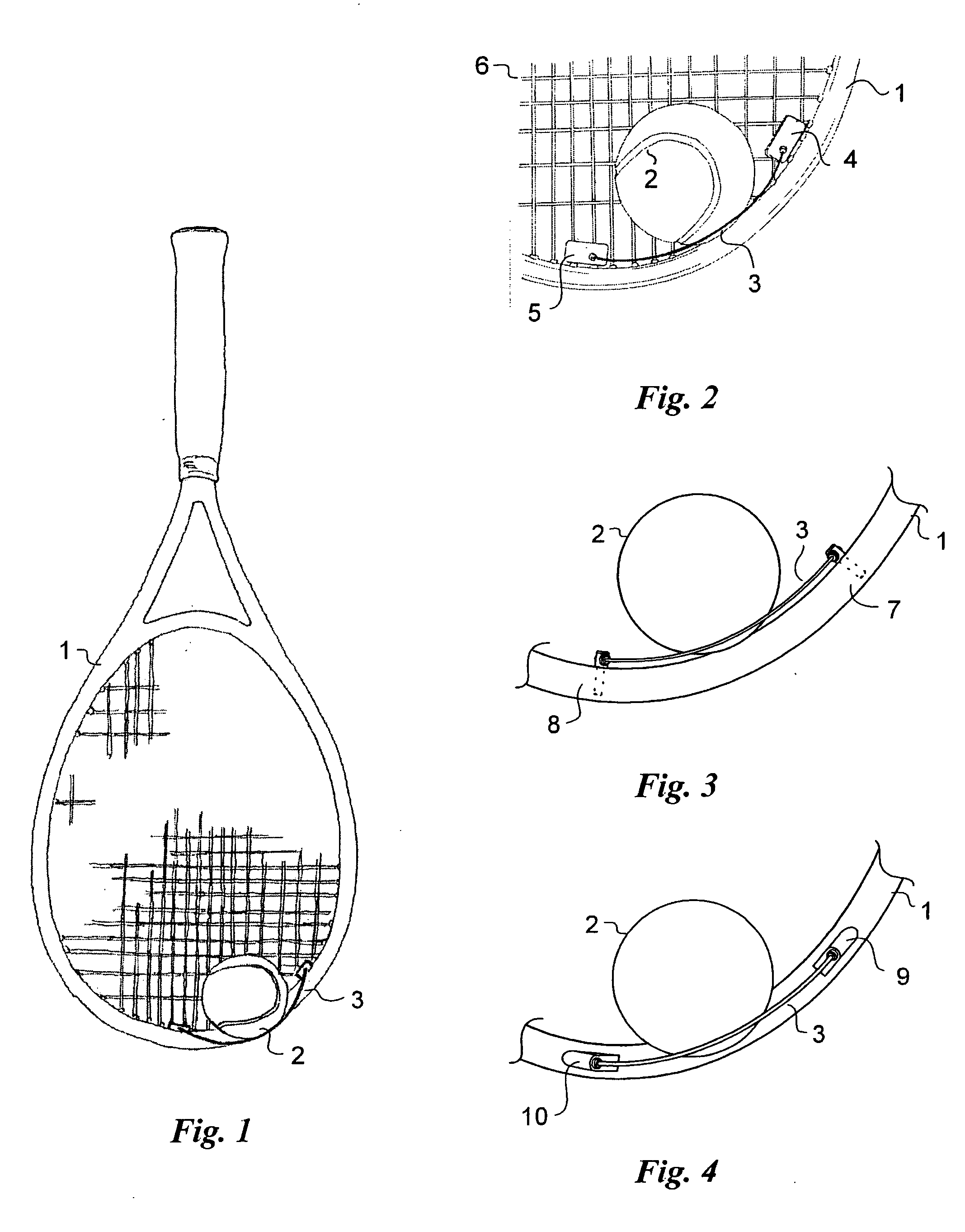
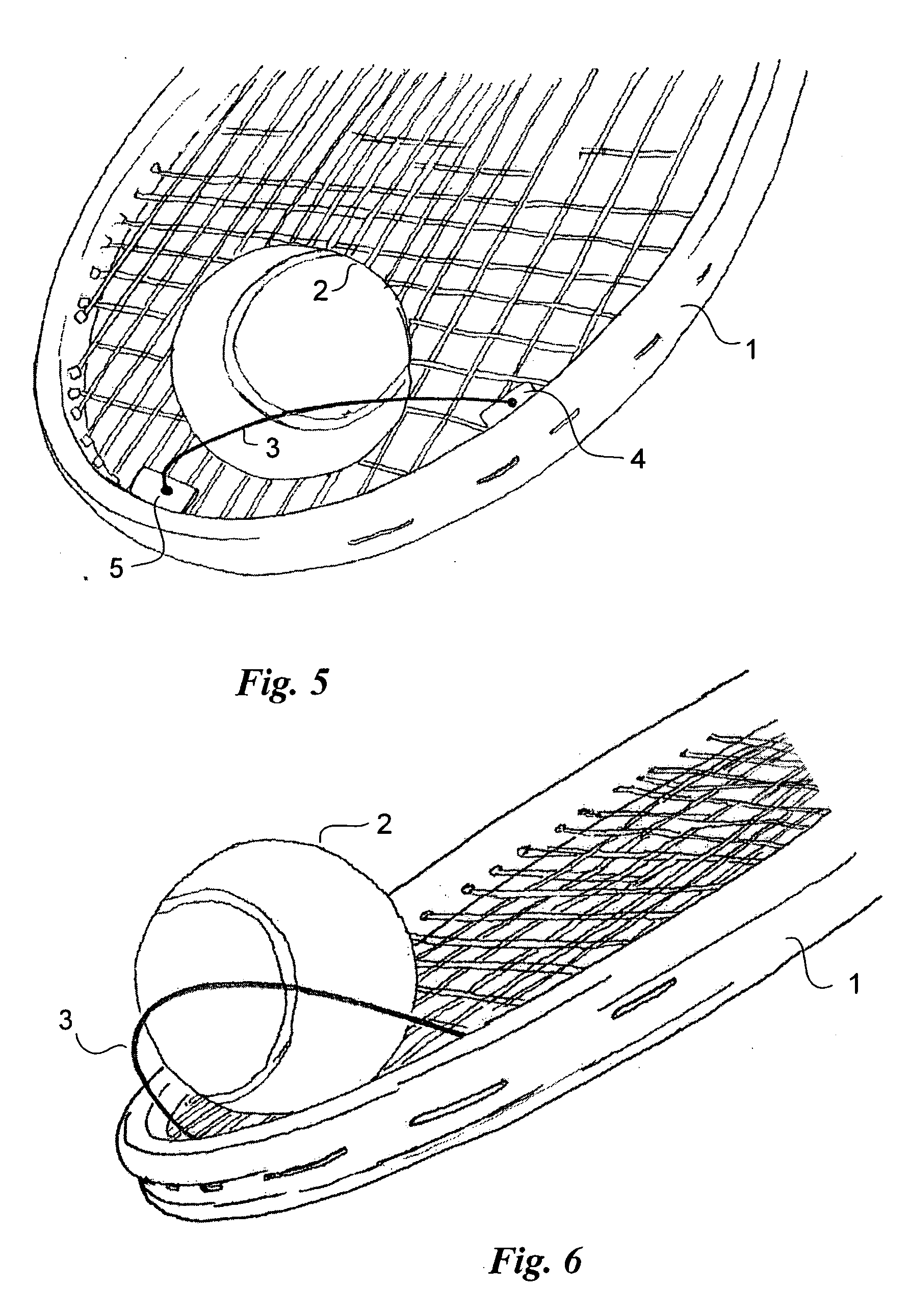
[0037]FIG. 3 shows the built-in Scoop from the same expanded viewpoint as the add-on Scoop of FIG. 2 but with the racquet strings omitted for clarity. This built-in Scoop differs from the add-on Scoop in that the spring wire 3 is supported by two receptacle mounts 7 and 8 that are built into the inside edge of the racquet frame 1. A plug affixed to one end of the initially straight spring wire 3 is inserted into one receptacle 7; the wire is then deformed, that is, bent by bringing the second end closer to the fixed end, so that a plug on the second end can be inserted into a second receptacle 8. As above, the spacing of the receptacles and the length of the wire cooperate so that an approximately parabolic loop is formed, which can then be used to scoop up the tennis ball. One advantage of this embodiment is that because the receptacles mount in holes on the inside rim of the racquet that are in line with the string holes, there is little likelihood that these additional two holes ...

second embodiment

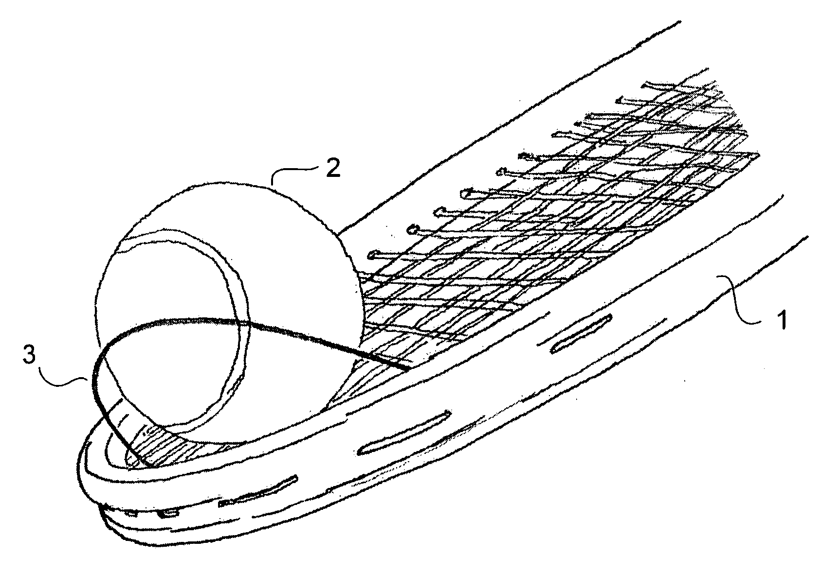
[0038]FIG. 4 shows the built-in Scoop, this one having resilient receptacle mounts 9 and 10 mounted on an outer edge of the frame of the racquet. Again, a fitting on one end of the initially straight spring wire 3 is inserted into one receptacle 9; the wire is then deformed to allow insertion of the other end into the other receptacle 10. The spacing of the receptacles and the length of the wire cooperate so that an approximately parabolic loop of wire is formed, which is then used to scoop up the tennis ball. This embodiment works exceptionally well in practice but may involve some additional consideration of the structural integrity of the racquet frame.

[0039] Although the add-on Scoop and the two built-in Scoops differ in the means employed to support the spring wire, the resulting shape and position of the wire loop formed is substantially the same and the wire loop is used in substantially the same manner to pick up a tennis ball. Three different physical embodiments are disclo...


PUM


Abstract

A spring wire loop is affixed to a tennis racquet to enable a player to conveniently scoop a tennis ball off the playing surface and retrieve it. In an add-on embodiment, the loop can be affixed by mounts secured to the strings of an existing racquet; alternatively, the loop can be secured to mounts built into the racquet at manufacture.

Description

CROSS-REFERENCE TO RELATED APPLICATION [0001] This application claims priority from provisional application Ser. No. 60 / 623,220, filed Nov. 1, 2004.FIELD OF THE INVENTION [0002] The present invention relates to a novel device and method for a tennis (or other racquet sport) player to retrieve a ball from the court surface with high style and minimal effort. BACKGROUND OF THE INVENTION [0003] The challenge of picking up a tennis ball from the playing surface is not a great one. Beginning tennis players quickly learn to pick up a ball by rolling it up against the side of their shoe. Many experienced players can pick it up by striking down on the ball with the racquet and then synchronously increasing the height of the bounce until it is high enough to catch. However, because the former method is awkward and the latter method difficult, it is not uncommon for players to simply stoop over to pick up the ball, which can be a nuisance over the course of a long playing session. [0004] A nu...

Claims


Application Information

Patent Timeline
IPC IPC(8): A63B49/02A63B49/00
CPCA63B47/02A63B61/00A63B2243/0083A63B2102/02
Inventor BLADES, FREDERICK K.
Owner BLADES FREDERICK K
Why Eureka
Try Eureka