

Method for implementing a resonator under electrostatic forces
a resonator and electrostatic force technology, applied in the direction of instruments, devices using electric/magnetic means, acceleration measurement using interia forces, etc., can solve the problems of resonator drift error, high cost of resonator, high cost of associated control circuit, etc., and achieve great accuracy
- Summary
- Abstract
- Description
- Claims
- Application Information
AI Technical Summary
Benefits of technology
Problems solved by technology
Method used
Image

Examples
Embodiment Construction
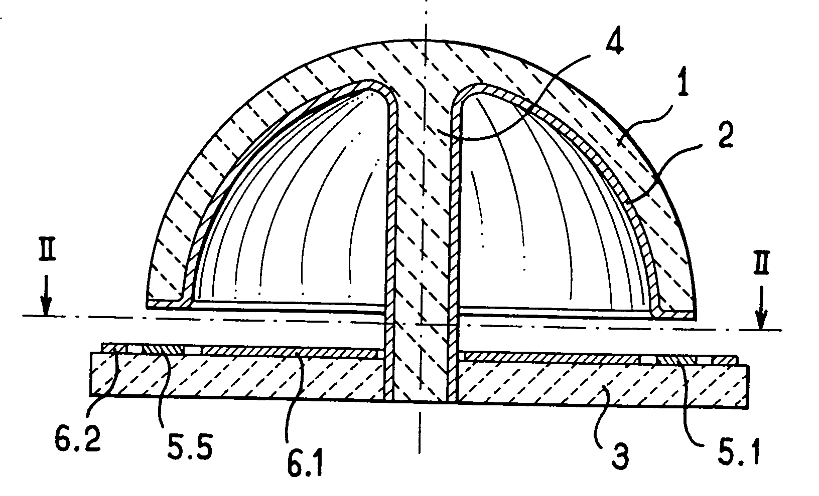
[0016] For a better understanding of the invention, the resonator is shown on a greatly enlarged scale with the thicknesses of the electrodes and the airgaps being exaggerated.
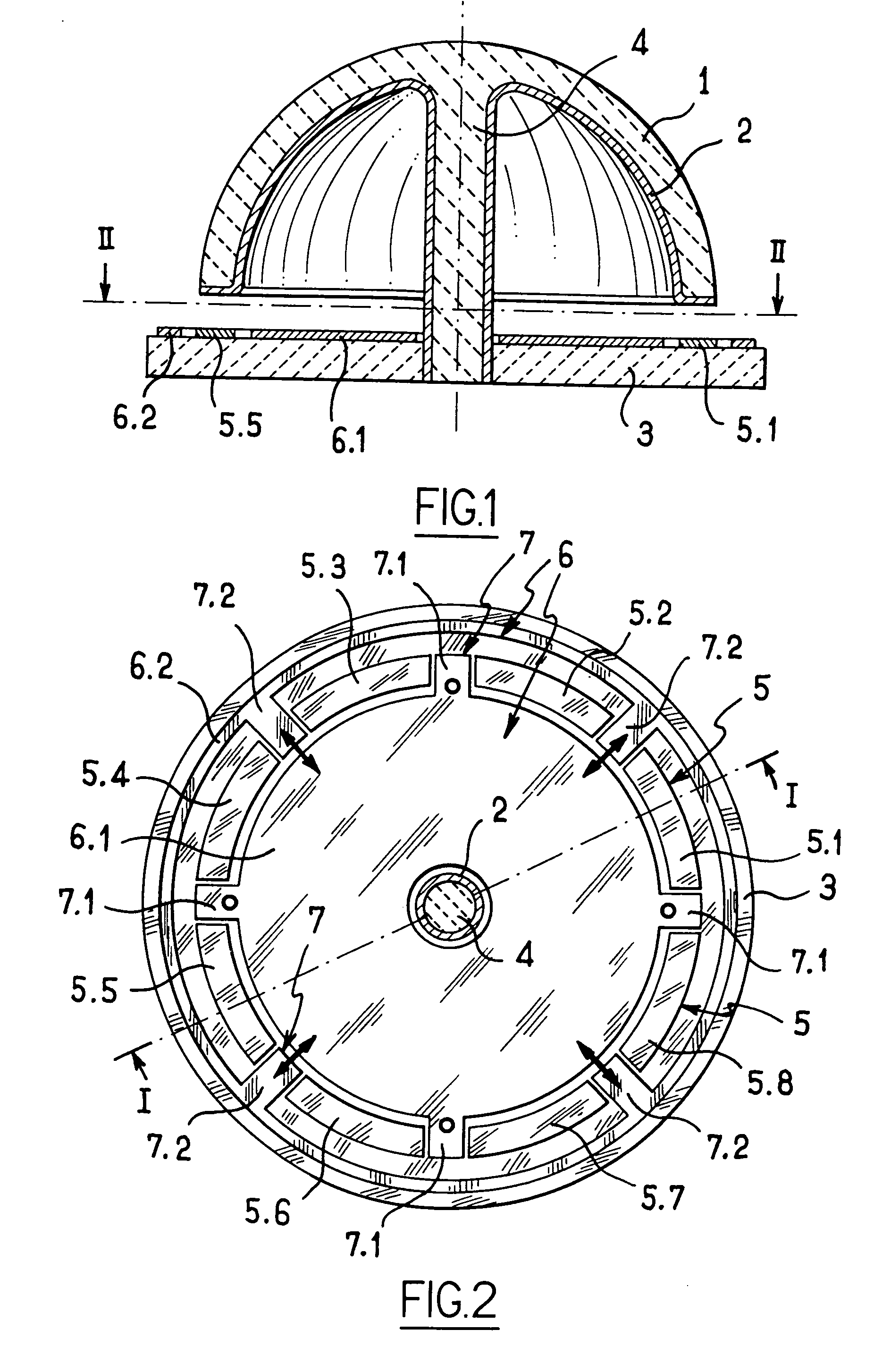
[0017] In the embodiment shown, the resonator comprises in conventional manner a hemispherical vibrating member 1, e.g. a bell made of silica and fixed by a rod 4 to a base 3. The inside surface of the bell 1 and its edge and also the rod 4 are covered in a layer of metal 2. The base 3 carries main electrodes given overall numerical reference 5 and individual references 5.1, 5.2, . . . , 5.8 enabling them to be identified individually. The electrodes 5 extend facing the edge of the vibrating member 1.
[0018] In the embodiment shown, the resonator also has a shield electrode given overall reference 6, which electrode is subdivided into two portions 6.1 and 6.2 each comprising four auxiliary electrodes given overall numerical reference 7 and particular numerical references 7.1 for the auxiliary electrodes of th...
PUM
 Abstract
Description
Claims
Application Information