Parallax barrier element, method of producing the same, and display device
a technology of parallax and barrier element, which is applied in the direction of optics, instruments, optics, etc., can solve the problems of wiring breakage, inability to switch between three-dimensional images and two-dimensional images, and inability to obtain bright two-dimensional images, etc., to achieve excellent light shielding function and simplify fabrication process.
- Summary
- Abstract
- Description
- Claims
- Application Information
AI Technical Summary
Benefits of technology
Problems solved by technology
Method used
Image
Examples
embodiment 1
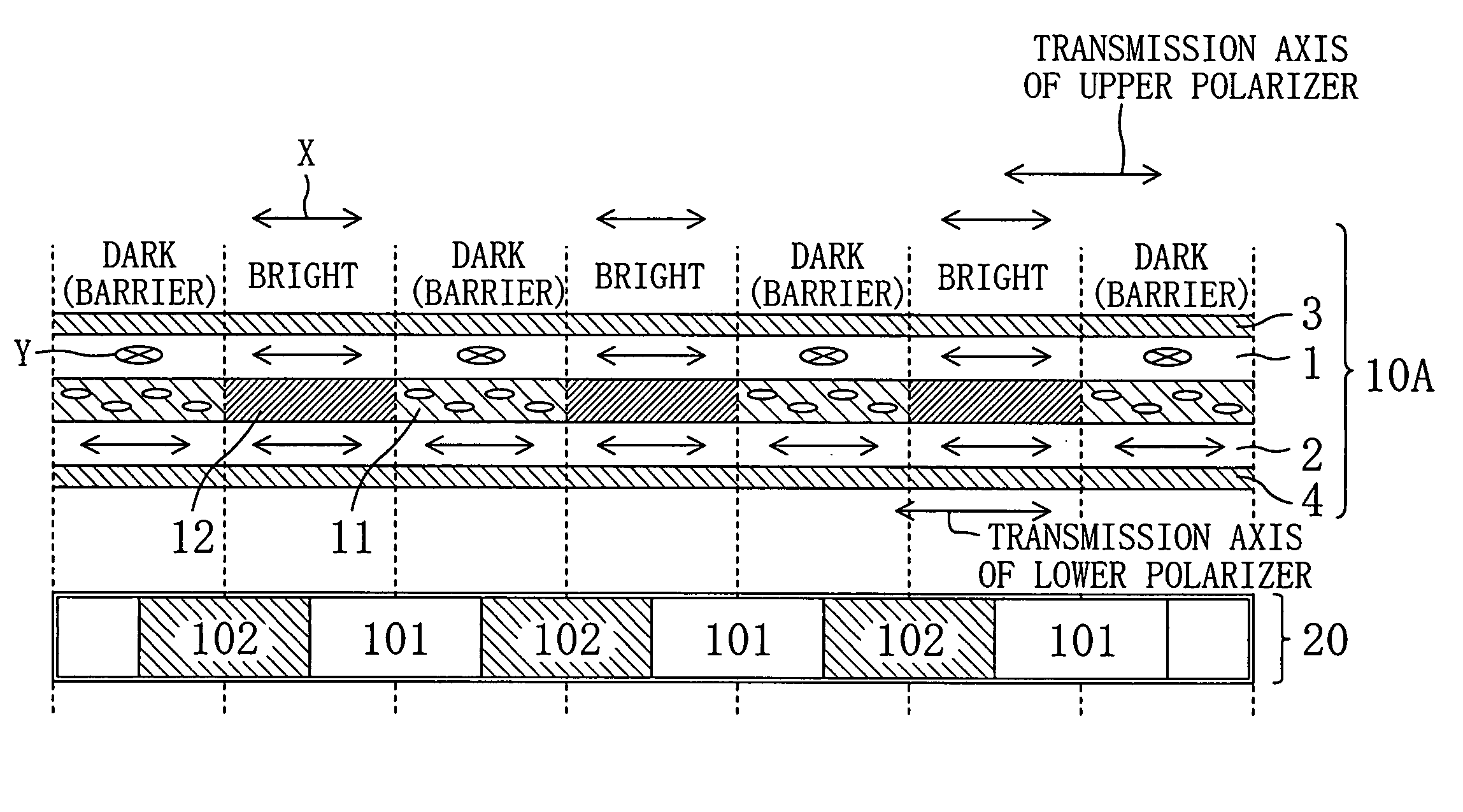
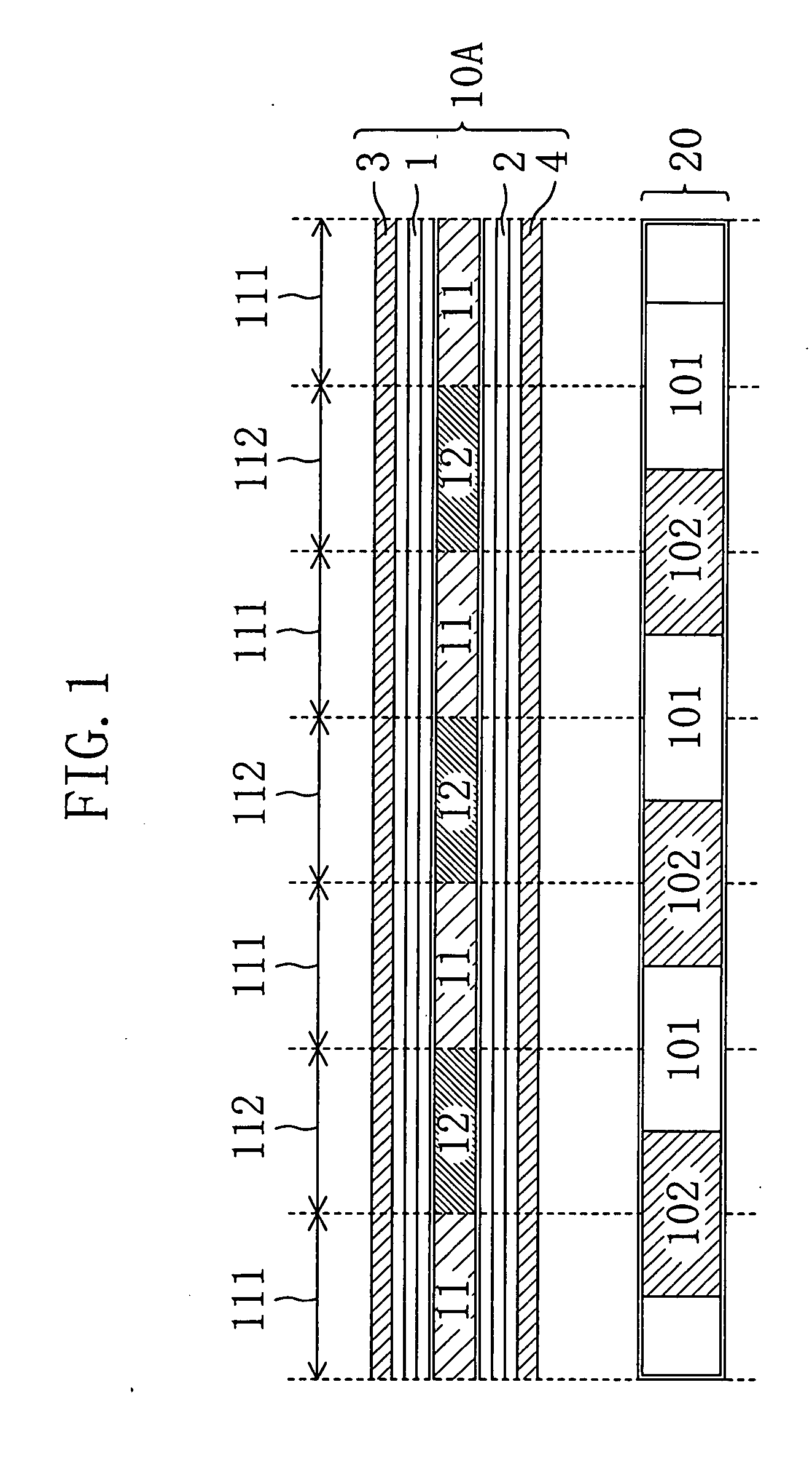
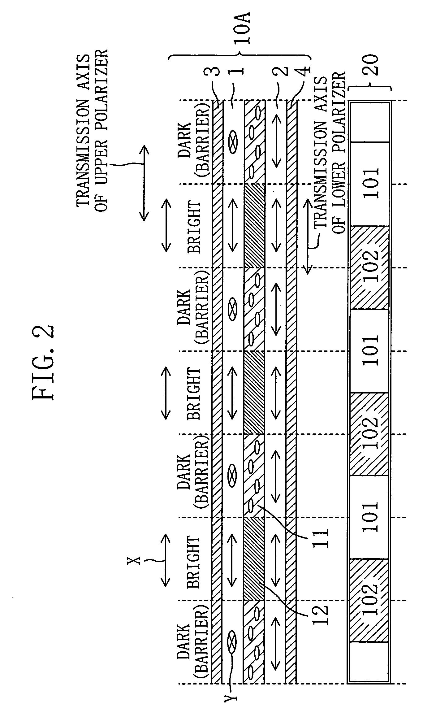
[0055]FIG. 1 is a cross-sectional view schematically showing a stereoscopic image display apparatus according to a first embodiment. The stereoscopic image display apparatus of this embodiment includes: a parallax barrier device 10A having a light-shielding function; an image display device 20 provided at the rear of the parallax barrier device 10A (at the side thereof opposite to a viewer: the same hereinafter); and a backlight (not shown) provided at the rear of the image display device 20. The image display device 20 includes: pixel parts 101 for displaying a right-eye image; and pixel parts 102 for displaying a left-eye image.
[0056] The parallax barrier device 10A includes: a pair of transparent-electrode substrates 1 and 2 made of glass or the like and provided with, for example, transparent electrodes; and a pair of polarizers 3 and 4 placed at the outsides of the pair of transparent-electrode substrates 1 and 2, respectively. The transparent-electrode substrates 1 and 2 incl...
embodiment 2
[0068] In the first embodiment, the pair of polarizers 3 and 4 is used. However, an optical retardation plate such as a λ / 4 plate or a λ / 2 plate and a polarizer may be used in combination, as necessary. In a second embodiment, a principle of display by a stereoscopic image display apparatus using a λ / 2 plate as an optical retardation plate will be described. As in the first embodiment, a liquid crystal layer 11 of this embodiment is a liquid crystal layer exhibiting homogeneous alignment and containing a liquid crystal material whose dielectric-constant anisotropy is positive and has a retardation of λ / 2 when no voltage is applied.
[0069]FIG. 4 is a cross-sectional view showing a principle of a three-dimensional image display by a stereoscopic image display apparatus according to this embodiment. A principle of display when no voltage is applied to a liquid crystal panel 10A functioning as a parallax barrier device, i.e., when a three-dimensional display is produced, will be describ...
embodiment 3
[0077] In the first and second embodiments, the liquid crystal layer 11 exhibiting homogeneous alignment and containing a liquid crystal material whose dielectric-constant anisotropy is positive is used. In this embodiment, the liquid crystal layer 11 used in the first and second embodiments is replaced with a liquid crystal layer exhibiting homeotropic alignment and containing a liquid crystal material whose dielectric-constant anisotropy is negative. This liquid crystal layer exhibiting homeotropic alignment has a retardation of λ / 2 during application of a voltage.
[0078] As compared to the liquid crystal layer 11 exhibiting homogeneous alignment containing a liquid crystal material whose dielectric-constant anisotropy is positive, the liquid crystal layer 11 exhibiting homeotropic alignment and containing a liquid crystal material whose dielectric-constant anisotropy Δε is negative makes its alignment state exactly reversed between application of no voltage and application of a v...
PUM
 Abstract
Description
Claims
Application Information
 - R&D
- Intellectual Property
- Life Sciences
- Materials
- Tech Scout
- Unparalleled Data Quality
- Higher Quality Content
- 60% Fewer Hallucinations
Browse by: Latest US Patents, China's latest patents, Technical Efficacy Thesaurus, Application Domain, Technology Topic, Popular Technical Reports.
© 2025 PatSnap. All rights reserved.Legal|Privacy policy|Modern Slavery Act Transparency Statement|Sitemap|About US| Contact US: help@patsnap.com


