Autostereoscopic display

Active Publication Date: 2006-06-01
SAMSUNG ELECTRONICS CO LTD
View PDF8 Cites 47 Cited by
  • Summary
  • Abstract
  • Description
  • Claims
  • Application Information

AI Technical Summary

Benefits of technology

[0018] The present general inventive concept provides a 2D/3D switchable autostereoscopic display, which can swit

Problems solved by technology

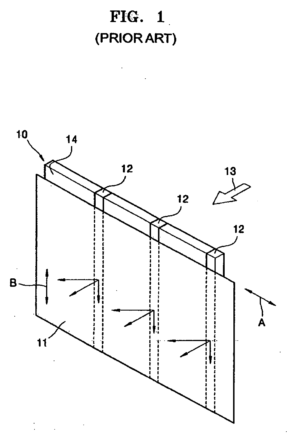
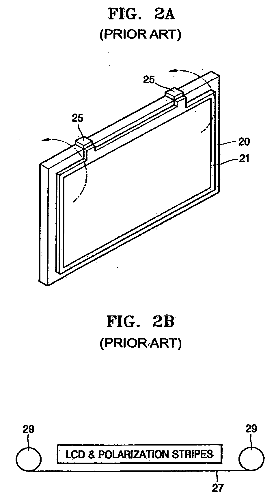
Accordingly, the conventional display is complex in structure and the complementary lenticular sheet, which is rotated on the hinges, requires a large amount of free space within and around the conventional display, thereby increasing an overall size of the conventional display.
In this case, a space for moving the polarization sheet 21 mounted on the hinges 25 becomes necessary, thereby leading to a bul

Method used


Image

  • Autostereoscopic display
  • Autostereoscopic display
  • Autostereoscopic display

Examples


Embodiment Construction

[0036] Reference will now be made in detail to the embodiments of the present general inventive concept, examples of which are illustrated in the accompanying drawings, wherein like reference numerals refer to the like elements throughout. The embodiments are described below in order to explain the present general inventive concept while referring to the figures.

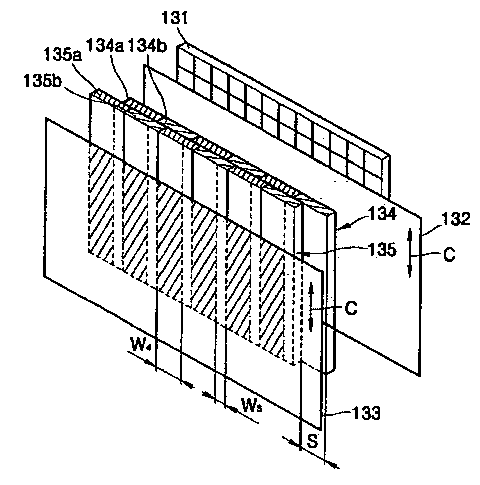
[0037]FIGS. 3A through 3F are perspective views illustrating an autostereoscopic display according to an embodiment of the present general inventive concept. Specifically, FIGS. 3A and 3B illustrate the autostereoscopic display respectively in a three dimensional (3D) mode and a two dimensional (2D) mode. FIGS. 3C and 3D illustrate an array of rotators respectively in the 3D mode and the 2D mode. FIGS. 3E and 3F illustrate an array of retarders respectively in the 3D mode and the 2D mode.

[0038] Referring to FIG. 3A, the autostereoscopic display includes a display device 31 to display an image including pixels in a row and ...


PUM


Abstract

An autostereoscopic display having an improved 2D/3D mode switchable structure. The autostereoscopic display includes: a display device to display an image, and a parallax barrier unit to transmit all incident light in a 2D mode, and to separate a left-eye image and a right-eye image by forming a barrier in a 3D mode. The parallax barrier unit includes: a polarizer disposed in an optical path of the image displayed by the display device to transmit light having a predetermined polarizer polarization direction, a first plane array including first birefringent elements, which change a polarization direction of light transmitted through the polarizer into a first direction, and second birefringent elements, which change a the polarization direction of the light transmitted through the polarizer into a second direction opposite to the first direction, the first and second birefringent elements alternating with each other, a second plane array facing the first plane array, and including third birefringent elements, which change a polarization direction of light transmitted through the first plane array into a third direction, and fourth birefringent elements, which change the polarization direction of the light transmitted through the first plane array into a fourth direction that is opposite from the third direction, the third and fourth birefringent elements alternating with each other, and an analyzer facing the second plane array to transmit only light having a predetermined analyzer polarization direction from among light transmitted through the second plane array, wherein at least one of the first and second plane arrays is movable to control relative positions of the first and second birefringent elements and the third and fourth birefringent elements to selectively display a 2D image or a 3D image.

Description

CROSS-REFERENCE TO RELATED APPLICATIONS [0001] This application claims the benefit of U.S. Provisional Patent Application No. 60 / 631,194, filed on Nov. 29, 2004, in the U.S. Patent & Trademark Office and Korean Patent Application No. 10-2005-0028065, filed on Apr. 4, 2005, in the Korean Intellectual Property Office, the disclosures of which are incorporated herein in their entirety by reference.BACKGROUND OF THE INVENTION [0002] 1. Field of the Invention [0003] The present general inventive concept relates to an autostereoscopic display that is switchable between three dimensional (3D) and two dimensional (2D) modes of operation, and more particularly, to an improved 2D / 3D switchable autostereoscopic display. [0004] 2. Description of the Related Art [0005] In general, autostereoscopic displays are used in game machines, computer monitors, notebook displays, mobile phones, and other applications to produce stereoscopic images. [0006] Autostereoscopic displays are typically mechanical...

Claims


Application Information

Patent Timeline
IPC IPC(8): G03B21/00G02B27/22G02B30/25G02B30/30
CPCG02B27/2214G02B27/26G02F2001/133638G02F2413/02G02F2413/07G02F2413/09H04N13/0409H04N13/0454H04N13/31H04N13/359G02B30/25G02F1/133638G02F1/133631G02B30/30A61H23/0263A61H7/007A61H2207/00A61H2205/083G02B30/27
Inventor SHESTAK, SERGEYKIM, DAE-SIK
Owner SAMSUNG ELECTRONICS CO LTD
Why Eureka
Try Eureka