System for controlling brightness flicker of parallax barrier LCD that has wide viewing angle and method thereof

a technology of parallax barrier and wide viewing angle, applied in the field of parallax barrier lcd, can solve the problems of brightness flicker, inability to implement stereoscopic image, and very limitative viewing angle of the viewer, and achieve the effect of minimizing brightness flicker and comforting feeling

Inactive Publication Date: 2011-01-13
NDIS CORP
View PDF19 Cites 49 Cited by
  • Summary
  • Abstract
  • Description
  • Claims
  • Application Information

AI Technical Summary

Benefits of technology

According to an embodiment of the present invention, it is possible to provide a comfortable feel to a viewer who views a stereoscopic image by minimizing...

Problems solved by technology

However, as shown in FIG. 4, when a viewing angle of the viewer deviates from a predetermined location, a part of an image is covered by the barrier, and as a result, the stereoscopic image is not implemented.
However, since the parallax barrier applied to the known stereoscopic display is fixed, a left-right viewing angle of the viewer is...

Method used


Image

  • System for controlling brightness flicker of parallax barrier LCD that has wide viewing angle and method thereof
  • System for controlling brightness flicker of parallax barrier LCD that has wide viewing angle and method thereof
  • System for controlling brightness flicker of parallax barrier LCD that has wide viewing angle and method thereof

Examples


first embodiment

As a first embodiment, an operation to minimize the brightness flicker by controlling the voltage applied to the split barrier electrodes will be described below.

The display panel formed of the liquid crystal display device maintains a balance state even when a driving voltage is not applied to the electrode (cell), but when the driving voltage is applied to the electrode (cell), alignment of liquid crystals is changed depending on the voltage to display an image by using the resulting change of a polarization state. On the contrary, when the driving voltage applied to each electrode (cell) is eliminated, the display panel is restored to the original balance state.

FIGS. 10 and 11 are graphs showing one example in which brightness flicker generated depending on driving voltage in a stereoscopic display is detected, and FIG. 12 as an experimental example of the present invention is a graph showing an example in which brightness flicker depending on each driving voltage in a stereoscop...

second embodiment

As a second embodiment, an operation to minimize the brightness flicker by modulating a phase of the voltage applied to the split barrier electrodes will be described below.

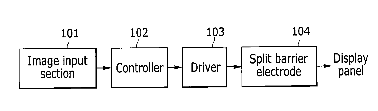
The controller 102 splits the permittivity curve depending on turn-on of the split barrier electrodes 104 by time while turning on / off the split barrier electrodes 104 by controlling the voltage applied to the split barrier electrodes 104 through the driver 103 in order to display the stereoscopic image, and applies an appropriate waveform by modulating the phase of the voltage applied depending on each of split timings so as to minimize the brightness flicker.

FIG. 13 is a diagram showing improvement of brightness flicker by phase modulation in a system for controlling brightness flicker of a parallax barrier LCD having a wide viewing angle according to an exemplary embodiment of the present invention, and FIG. 14 is a diagram showing control of phase modulation in a system for controlling brightness flicker of a...

third embodiment

A third embodiment shows a method of minimizing brightness flicker caused due to moire depending on a viewing angle.

In general, the split barriers are not continuously changed but are changed in a stepwise fashion depending on the number of split barriers. However, when the viewing angle of the viewer is changed, the brightness is continuously changed as shown in FIG. 8.

Although the brightness flicker caused due to moire depends on design and characteristics of the display, brightness flicker of approximately 30% is substantially generated depending on the change of the viewing angle. Therefore, in the present invention, the brightness flicker is minimized by controlling independent driving of the split barrier electrodes as shown in FIG. 15.

As shown in FIG. 15, one or more intermediate steps are provided while moving the split barriers to the right side or the left side in order to correct decreased brightness by changing the viewing angle of the viewer, thereby minimizing the brig...


PUM


Abstract

A system for controlling brightness flicker of a parallax barrier LCD having a wide viewing angle capable of minimizing brightness flicker by adjusting a permittivity curve depending on different times into a predetermined waveform when split barriers are on/off by movement of a viewer's viewing angle, and a method thereof. A method of controlling brightness flicker of a parallax barrier LCD having a wide viewing angle for controlling brightness of a display providing a stereoscopic image by acquiring a real-time image of a viewer, recognizing an image of the viewer and extracting locations and coordinates of eyes of the viewer, and controlling turn-on/off of split barrier electrodes.

Description

CROSS-REFERENCE TO RELATED APPLICATIONThis application claims priority to and the benefit of Korean Patent Application No. 10-2009-0063087 filed in the Korean Intellectual Property Office on Jul. 10, 2009, the entire contents of which are incorporated herein by reference.BACKGROUND OF THE INVENTION(a) Field of the InventionThe present invention relates to a parallax barrier LCD, and more particularly, to a system for controlling brightness flicker of a parallax barrier LCD having a wide viewing angle that is capable of minimizing the brightness flicker by adjusting a permittivity curve depending on different times into a predetermined waveform when split barriers are on / off by movement of a viewer's viewing angle, and a method thereof.(b) Description of the Related ArtVarious methods for a technology relating to a stereoscopic display using binocular disparity are being proposed. One of representative methods allows a viewer to acquire a cubic effect by installing a lenticular lens ...

Claims


Application Information

Patent Timeline
IPC IPC(8): G09G3/36G09G5/10G02B30/30
CPCG02B27/0093G02B27/2214G09G3/003G09G3/36H04N13/0477G09G2354/00G09G2356/00H04N13/0413G09G2320/0247H04N13/376H04N13/315G02B30/30H04N13/00G02F1/1335G02F1/1343G09G3/20G02B30/27
Inventor MIN, KWAN-SIKPARK, SANG HYUNKWON, SOON BUMJOO, HYONAMJEONG, DONG CHEOLCHO, TAI HOON
Owner NDIS CORP
Why Eureka
Try Eureka