Optical pickup apparatus for optical disc drive

Inactive Publication Date: 2006-05-11
SAMSUNG ELECTRONICS CO LTD
View PDF3 Cites 1 Cited by
  • Summary
  • Abstract
  • Description
  • Claims
  • Application Information

AI Technical Summary

Benefits of technology

[0010] An object of the present invention is to solve at least the above problems and/or disadvantages and to provide at least the advantages described below. Accordingly, an object of the present invention is to provide an optica

Problems solved by technology

When the optical pickup unit 30 cannot move smoothly due to the friction,

Method used


Image

  • Optical pickup apparatus for optical disc drive
  • Optical pickup apparatus for optical disc drive
  • Optical pickup apparatus for optical disc drive

Examples


Embodiment Construction

[0026] Reference will now be made in detail to embodiments of the present invention, examples of which are illustrated in the accompanying drawings, wherein like reference numerals refer to the like elements throughout. The embodiments are described below in order to explain the present invention by referring to the figures.

[0027] In the following description, same drawing reference numerals are used for the same elements even in different drawings. Also, well-known functions or constructions of an optical pickup unit of a general optical disc drive, as described in the related art, will not be described in detail.

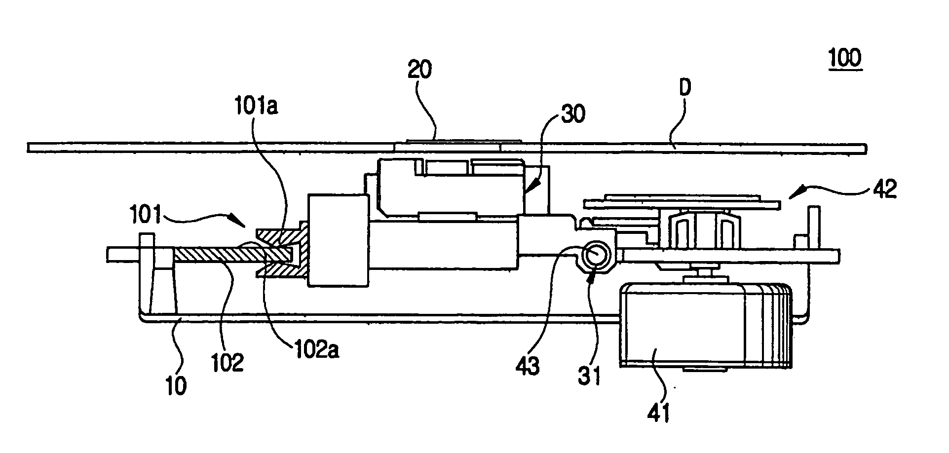
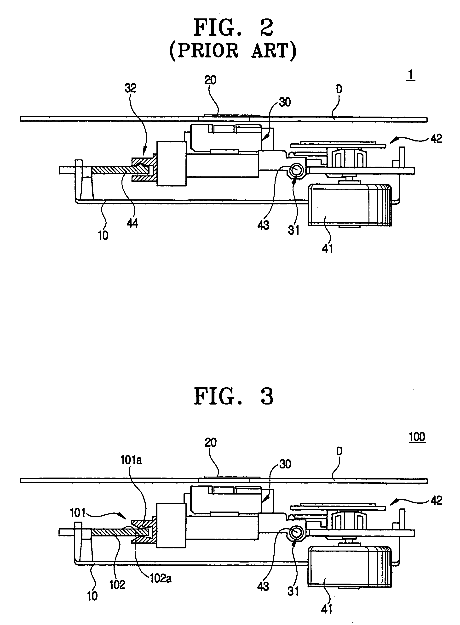
[0028] Referring to FIGS. 3-5, an optical pickup unit 30 provided to an optical pickup apparatus 100 is connected at one end to a main guide 43 by a sliding bearing 31. An auxiliary guide receiving groove 101 provided at the other end of the optical pickup unit 30 guides a path for the optical pickup unit 30 to move near to and away from the turntable 20 in line-contact ...


PUM


Abstract

An optical pickup apparatus for an optical disc drive, including: a base; a turntable disposed above the base and which rotates an optical disc; an optical pickup unit which reciprocates with respect to the turntable in a radial direction of the turntable; a driving part which moves the optical pickup unit with respect to the turntable; and a guide unit having an auxiliary guide which supports an end of the optical pickup unit and which guides the optical pickup unit along a moving path. The optical pickup unit and the auxiliary guide are in line-contact with each other.

Description

BACKGROUND OF THE INVENTION [0001] 1. Field of the Invention [0002] The present invention relates to an optical pickup apparatus for an optical disc drive. More particularly, the present invention relates to an optical pickup apparatus for an optical disc drive, which has an improved receiving unit in an optical pickup unit for smooth movement thereof so as to enhance an endurance period thereof. [0003] 2. Description of Related Art [0004] Generally, an optical disc player records information on an optical disc such as a compact disc (CD), a CD read-only memory (CD-ROM), a digital video disc (DVD), and a DVD-ROM, and reproduces the recorded information. Referring to FIGS. 1 and 2, an optical disc player includes an optical pickup apparatus 1 for recording and reproducing information by irradiating a light on a recording surface of the optical disc. [0005] As shown in FIGS. 1 and 2, the optical pickup apparatus 1 includes a base 10, a turntable 20 disposed over the base 10, an optica...

Claims


Application Information

Patent Timeline
IPC IPC(8): G11B7/08G11B7/085G11B7/09
CPCG11B7/08582
Inventor PARK, SOO-HANKIM, BONG-GINAM, DO-HOAN
Owner SAMSUNG ELECTRONICS CO LTD
Why Eureka
Try Eureka