Printer

Active Publication Date: 2006-05-18
OCE TECH
View PDF3 Cites 1 Cited by
  • Summary
  • Abstract
  • Description
  • Claims
  • Application Information

AI Technical Summary

Benefits of technology

[0005] In one embodiment, the element is resilient in the said axial direction. The advantage of this is that the core can be easily placed in the supply unit between the element and the stop, while a pressure application force is at the same time provided in the axial direction.
[0006] In another embodiment, in which the support means are distributed over a first and second support member, the stop is a part of the second support member. This embodiment has the advantage that the risk of connection faults is further reduced.
[0007] In another embodiment, the supply unit comprises two elements for exerting a force on the core in the axial direction. This embodiment offers the advantage that a force can be exerted on the core on both sides of the core shaft. As a result, a greater force can be exerted in the axial direction, thus reducing the risk of inducing an oscillation of the core. This further reduces the risk of connection faults.
[0008] In another embodiment, the two elements are spaced apart by an amount substantially equal to the diameter of the core. The force can thus be exerted on the edge of the core, distributed over two opposite points on the edge. This is a simple matter of providing adequate and reliable pressing of the core against the stop. In one embodiment, the elements are resiliently mounted wheels. In this case the core can rotate freely over the wheels while they exert a force on the core in the axial direction. As a result of the possibility of free rotation, the frictional force between the elements and the core during the rotation thereof are minimised. The incidence of irregularities in the speed at which the substrate is unwound can thus be prevented.
[0009] In one embodiment, the supply unit includes a drawer containing the sup

Problems solved by technology

One problem with this known printer is the incidence of visible connection errors between the different sub-images.
Such faults may have a very disturbing effect on the printed image, particularly

Method used


Image

  • Printer
  • Printer
  • Printer

Examples


Example

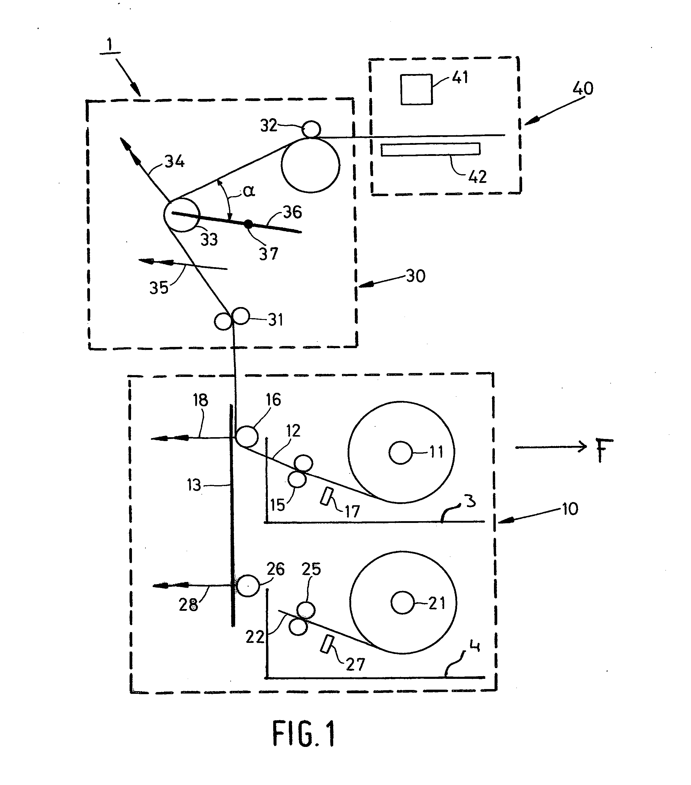
[0016]FIG. 1 is a diagram showing a printer according to the present invention. The printer is provided with a supply unit 10 which serves for storage and delivery of the substrate for printing. In addition, the printer includes transport unit 30 which transports the substrate from the supply unit 10 to the print unit 40. Unit 30 also ensures accurate positioning of the substrate in the print zone formed between the print surface 42 and the inkjet printhead 41. In this embodiment, print unit 40 is a conventional engine comprising printhead 41 which is constructed from a number of loose sub-heads, each for one of the colors black, cyan, magenta and yellow. A printhead of this type is described in detail in European patent application EP 1,378,360. Printhead 41 has only a limited print range so that it is necessary to print the image on the substrate in various sub-images. For this purpose, the substrate is transported in increments in each case in the transit direction (subscan direc...


PUM


Abstract

A printer including a printhead which is displaceable at the level of a print surface in a main scanning direction and in a sub-scanning direction with respect to a substrate situated in the print surface, and a supply unit for storing the substrate which is disposed on a core and delivering the substrate for transport to the print surface, said supply unit including support means for supporting the core at its end portions so that the core, while being supported, can rotate with the unwinding of substrate from the core, said support means containing an element for exerting a force on the core in the axial direction during the rotation thereof, whereby the core is pressed against a stop which occupies a substantially fixed position in the axial direction with respect to the print surface.

Description

BACKGROUND OF THE INVENTION [0001] The present invention relates to a printer containing a printhead which is displaceable at the level of a print surface in a main scanning direction and in a sub-scanning direction with respect to a substrate situated in the print surface, and a supply unit for storing the substrate and delivering the substrate for transport to the print surface, which unit includes means to support a core in the vicinity of its ends, such that the core, while being supported, can rotate to unwind the substrate rolled on said core. [0002] A printer of this kind is generally known from the prior art. In this printer, the substrate is stored on a roll, particularly a core on which 50 to 200 meters of a specific type of substrate are rolled. To print the substrate, the substrate is unwound from the core in the printer as required, and the free end is transported to the print surface. There at least a part of the image for printing is formed by moving the printhead wit...

Claims


Application Information

Patent Timeline
IPC IPC(8): B41J2/01
CPCB41J15/042
Inventor VAN SOEST, HENDRIKUS J. J.COENEN, JEROEN J. G.
Owner OCE TECH
Why Eureka
Try Eureka