Hand cutter with a retractable blade

Active Publication Date: 2018-10-04
RITESAFETY PROD INT
View PDF16 Cites 2 Cited by
  • Summary
  • Abstract
  • Description
  • Claims
  • Application Information

AI Technical Summary

Benefits of technology

[0006]The main object of the present invention is to provide an improved hand cutter with a retractable blade, which can be easily placed in a stable fully extended position without requiring a large forward motion of the users thumb or other finger and which is automatically retracted and placed back into the original position after performing the cut. This is achieved by providing the hand cutter with an actuator assembly, a gear assembly and a blade assembly which are coupled by respective coupling mechanisms. A movement of the actuator assembly is transmitted to the blade assembly via the gear assembly, whose gear ratio allows the blade to extend from

Problems solved by technology

One issue with currently known knives is to provide an extended position in which the blade is not accidentally retracted due to a quick motion or jolt created by the user.
Some such knives automatically retract before they were used for cutting due to wear of the parts used in the hand cutter.
In addition, when such knives are used for a long period of

Method used


Image

  • Hand cutter with a retractable blade
  • Hand cutter with a retractable blade
  • Hand cutter with a retractable blade

Examples


Example

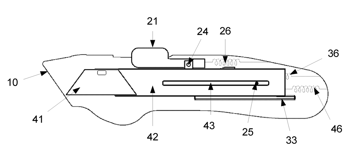
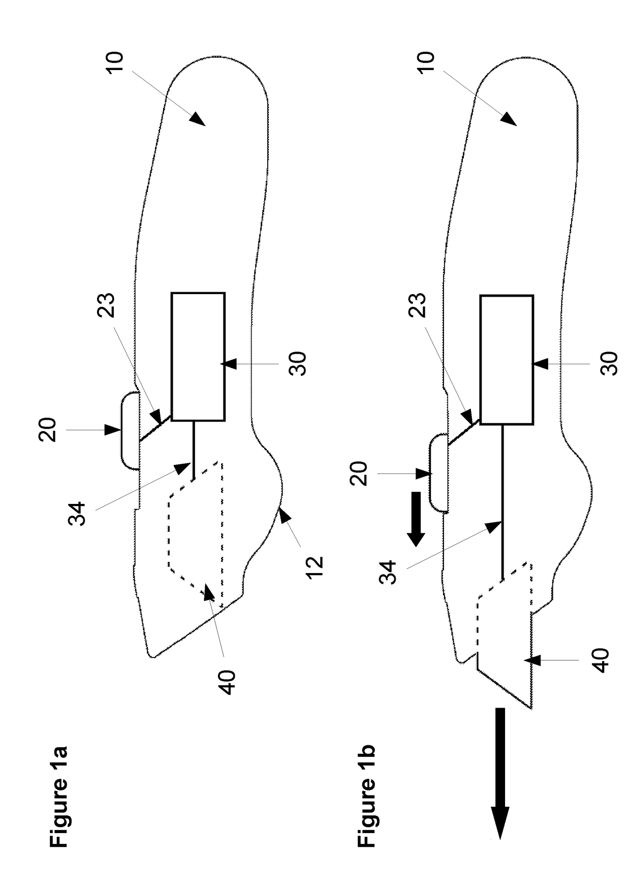
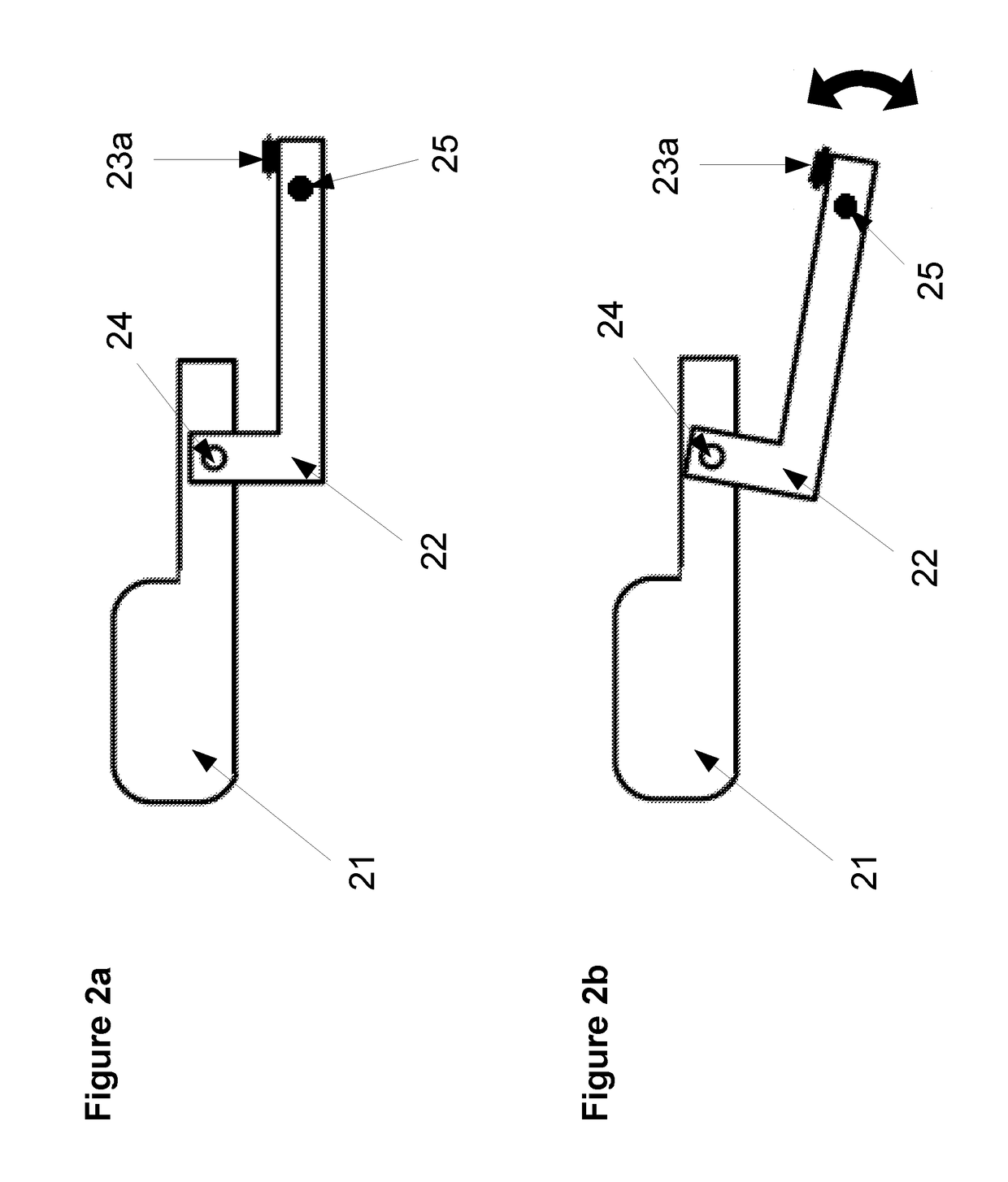
[0026]The present hand cutter comprises a housing 10, an actuator assembly 20, a gear assembly 30 and a blade assembly 40 (FIG. 1a). The actuator assembly 20 and the gear assembly 30 are releasably coupled via first coupling means 23, and the gear assembly 30 and the blade assembly 40 are releasably coupled via a second coupling means 34. Both actuator assembly 20 and blade assembly 40 are slidable within the housing in the longitudinal direction of the hand cutter (FIG. 1b). Thus, the actuator assembly 20 is slidable between a first actuator position at the rear of the hand cutter (FIG. 1a) and a second actuator position at the front of the hand cutter (FIG. 1b). Similarly, the blade assembly 40 is slidable between a retracted position (FIG. 1a) and a first extended position (FIG. 1b). When the hand cutter is not in use, the actuator assembly 20 and the blade assembly 40 are in the first and retracted position respectively, and the blade is concealed in the housing (FIG. 1 a). As s...


PUM


Abstract

A hand cutter comprising a housing, a blade assembly, an actuator assembly, a gear assembly and a retraction means with the gear assembly connecting the actuator assembly to the blade assembly in such a manner that a movement of said actuator slide is transmitted to said blade assembly via said gear assembly with a gear ratio of said gear assembly such that moving said actuator slide moves said blade assembly by a larger distance.

Description

FIELD OF THE INVENTION[0001]The present invention generally relates to a hand cutter with a retractable blade according to the preamble of patent-claim 1.BACKGROUND OF THE INVENTION[0002]Hand cutters with safety features for protection are well known and have been present in the market for many years. The need for cutting tools with the highest possible protection for the user is increasing in today's market, where many goods are shipped throughout the world for which the packaging needs to be removed safely and swiftly. Solutions range from low cost devices with integrated blades to more sophisticated hand cutters with replaceable blades. Several means are known for providing safe handling of the cutters, both for when these are in use, as well as when they are not in use. One common solution is to stow the cutting blade within the housing of the cutting tool when it is not in use. The blade is extended out of the housing for cutting before it is used and is stowed away into the ho...

Claims


Application Information

Patent Timeline
IPC IPC(8): B26B1/08
CPCB26B1/08B26B5/001B26B7/00B26B5/003
Inventor LANDWEHR, THOMAS JAY
Owner RITESAFETY PROD INT
Why Eureka
Try Eureka