Heat source unit of refrigerating apparatus

Inactive Publication Date: 2015-10-01
DAIKIN IND LTD
View PDF12 Cites 2 Cited by
  • Summary
  • Abstract
  • Description
  • Claims
  • Application Information

AI Technical Summary

Benefits of technology

[0031]In the heat source unit of a refrigerating apparatus according to the thirtee

Problems solved by technology

In this case, the operation of placin

Method used


Image

  • Heat source unit of refrigerating apparatus
  • Heat source unit of refrigerating apparatus
  • Heat source unit of refrigerating apparatus

Examples


Example

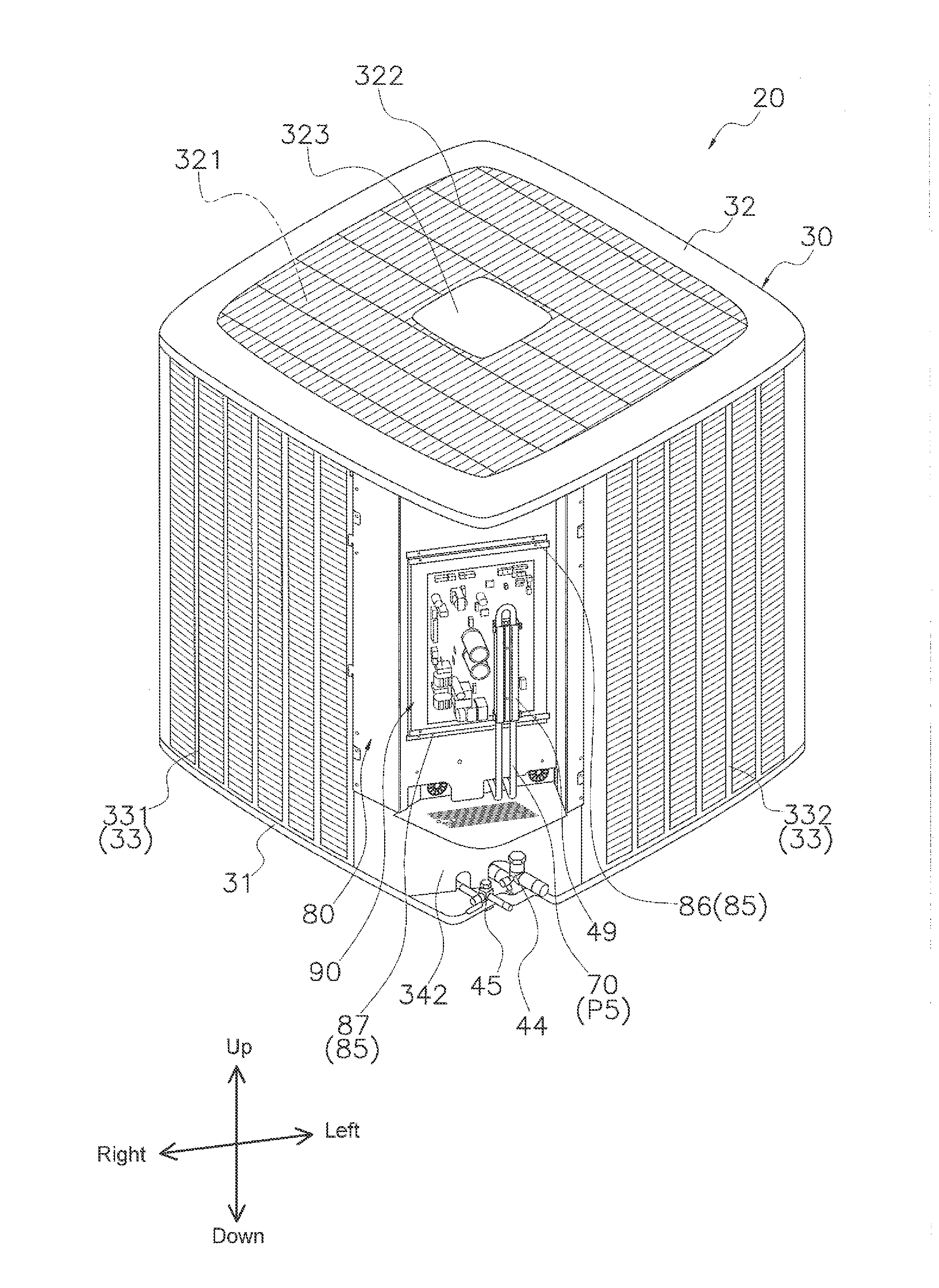
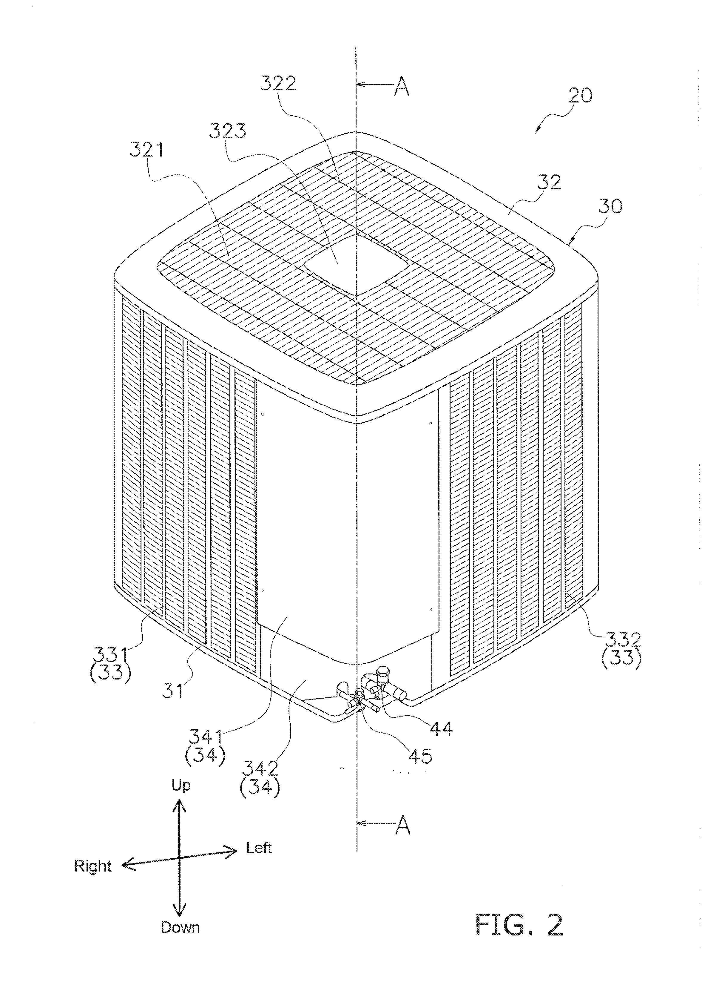
[0064]A heat source unit 20 according to one embodiment of the present invention is described below. The embodiment below is a specific example of the present invention and is not a limitation of the technical scope of the present invention. Suitable modifications may be made within a scope not deviating from the gist of the invention. In the embodiment below, the directions “up,”“down,”“front (front face),”“back (back face),”“left,” and “right” signify the directions illustrated in FIGS. 2 to 25. These directions are directions based on a main face 50a of a partitioning plate 50 (to be described) in a placed state.

[0065](1) Configuration of the Air-Conditioning Apparatus 100

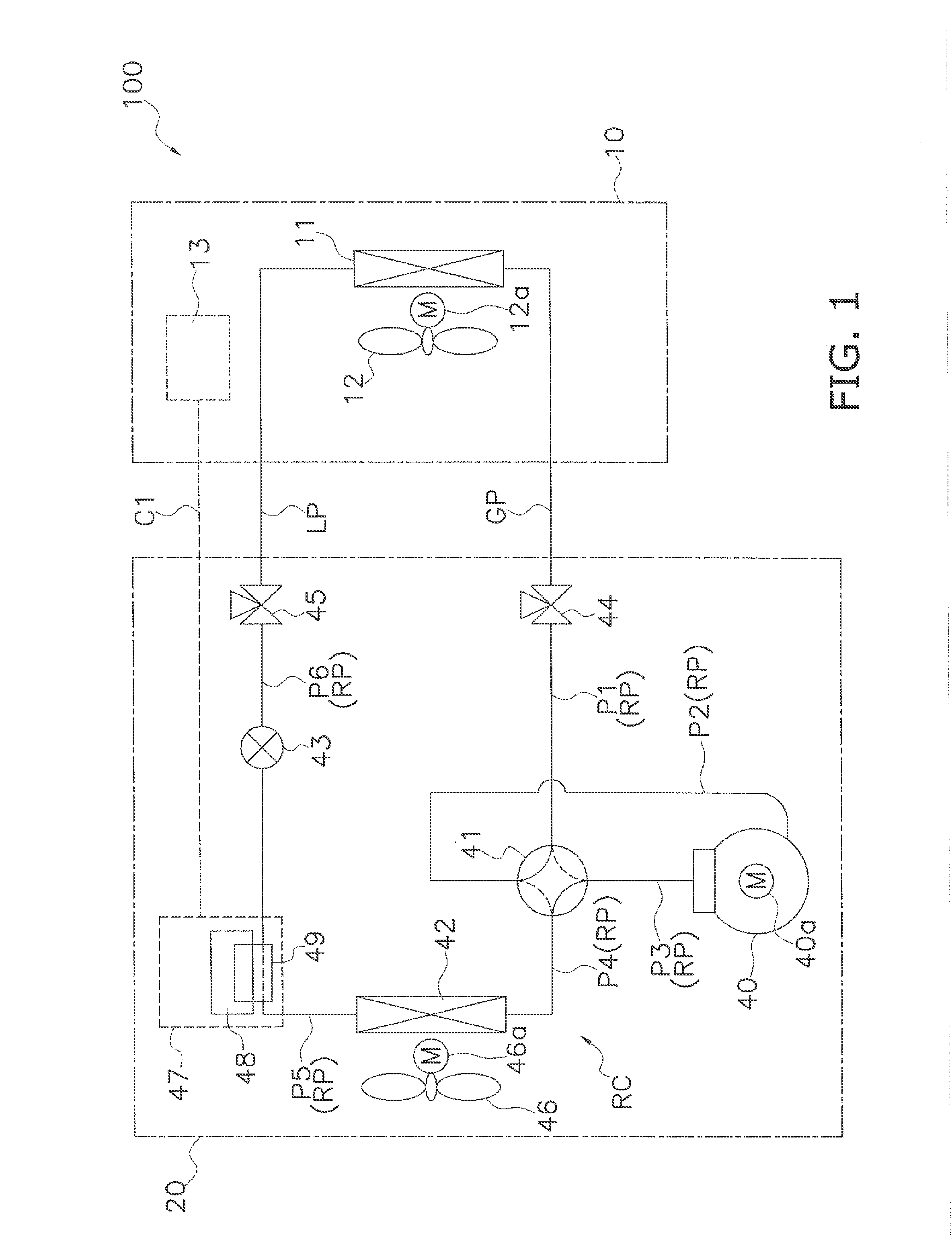
[0066]FIG. 1 is a schematic diagram of an air-conditioning apparatus 100 including a heat source unit 20 according to one embodiment of the present invention.

[0067]The air-conditioning apparatus 100 is an apparatus for performing a cooling operation or a warming operation to realize air conditioning of an object...


PUM


Abstract

A heat source unit of a refrigerating apparatus includes a heat exchanger, an actuator, an electrical component controlling the actuator, a casing, and a partitioning plate. The casing has bottom and top plates with a vent on the top plate. The heat exchanger has first, second, third and fourth side face parts. The actuator is disposed in a first space surrounded by the first to fourth side face parts, and the partitioning plate. The electronic component is disposed in a second space partitioned from the first space by the partitioning plate. The second space is in a corner formed by the first and second side face parts. The partitioning plate is positioned between end parts of the first and fourth side face parts, and at least a portion is inserted between the bottom and top plates and fixed in a placed state.

Description

TECHNICAL FIELD[0001]The present invention relates to a heat source unit of a refrigerating apparatus.BACKGROUND ART[0002]Heat source units of a refrigerating apparatus typically have a partitioning plate provided inside a casing.SUMMARY OF THE INVENTION[0003]In the heat source unit as described above, there is a case where the partitioning plate must be placed after placing the bottom plate and the top plate in the manufacturing process. In this case, the operation of placing the partitioning plate is difficult.[0004]Therefore, with a heat source unit of the present invention, at least a portion of a partitioning plate is inserted from the side direction with regard to a main face of the partitioning plate in a placed state, and then fixed.[0005]Specifically, a heat source unit of a refrigerating apparatus according to a first aspect comprises a heat exchanger, an actuator, an electrical component, a casing, and a partitioning plate. The electrical component controls driving of an ...

Claims


Application Information

Patent Timeline
IPC IPC(8): H05K7/20
CPCH05K7/20272H05K7/20254H05K7/20354H05K7/202
Inventor HAYAKAWA, HIRONORI
Owner DAIKIN IND LTD
Why Eureka
Try Eureka