
Prevention of ventilator associated pneumonia (VAP)
a technology of ventilator and associated pneumonia, which is applied in the field of patient treatment, can solve the problems of increasing morbidity and mortality, difficult and expensive diagnosis of vap, and the cost of diagnosing and treating vap exceeds 1.1 billion dollars annually, so as to reduce or prevent colonization of the respiratory tract with gastrointestinal organisms, and reduce or prevent colonization of the respiratory tra
- Summary
- Abstract
- Description
- Claims
- Application Information
AI Technical Summary
Benefits of technology
Problems solved by technology
Method used
Image

Examples
example 1
Leakage Experiment
[0055] Experimentation regarding anti-VAP devices and / or anti-VAP materials was performed as follows.
[0056]FIG. 3 shows a screening methodology reported in other studies that uses the barrel of a 20 cc syringe to act as the trachea. It is intubated with an endotracheal tube followed by inflation of the cuff and introduction of dye above the balloon. A 7 mm ETT was used. Leakage of dye around the balloon can then be observed for. Leakage of dye is seen (FIG. 3) when the balloon is filled with 10 cc air.
[0057] In FIG. 4, another 7 ETT is used but before insertion into the “trachea” it was placed through a simple piece of a latex rubber drain Inflation of the native balloon followed by instillation of dye was then performed. There is no evidence of leakage (FIG. 4), even with manipulation of the proximal ETT. Identical results have been found using the finger portion of simple latex gloves. The tubular member may be constructed in such a manner that it comes with i...
example 2
[0058]FIG. 5 shows an inventive open ended sleeve 500 or condom to be placed over an ETT prior to intubation. A portion 501 of the sleeve 500 goes over the ETT balloon and expands as the balloon expands.
[0059] Modification of the end of the sleeve 500 allows for the native balloon to be covered with a material that would not lead to formation of channels between the ETT attachment and the tracheal mucosa when the native balloon is inflated. The sleeve 500 may be embedded with antimicrobials / bacteriostatic agents and anaesthetics. Materials used for forming the sleeve 500 preferably are resistant to formation of biofilms.
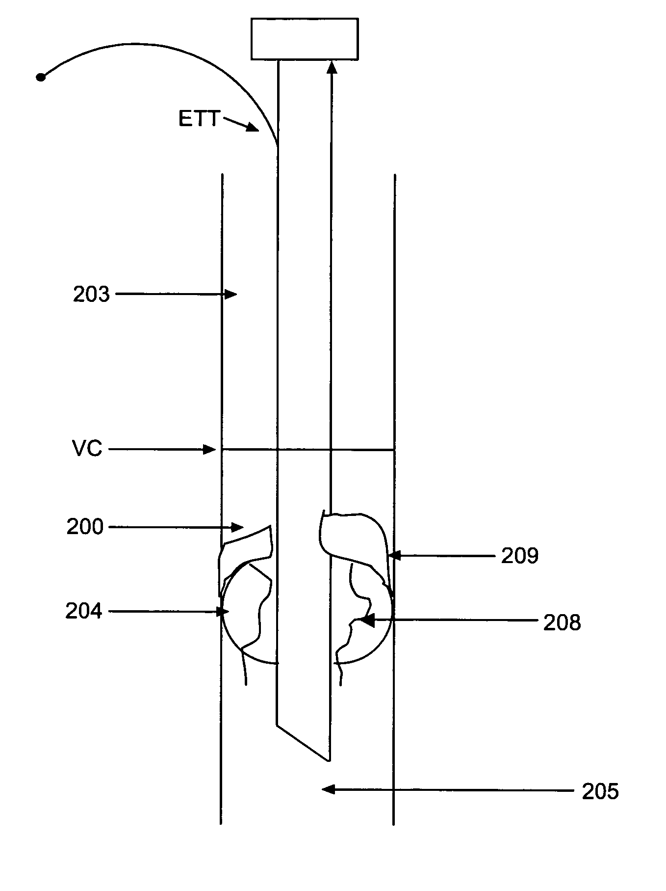
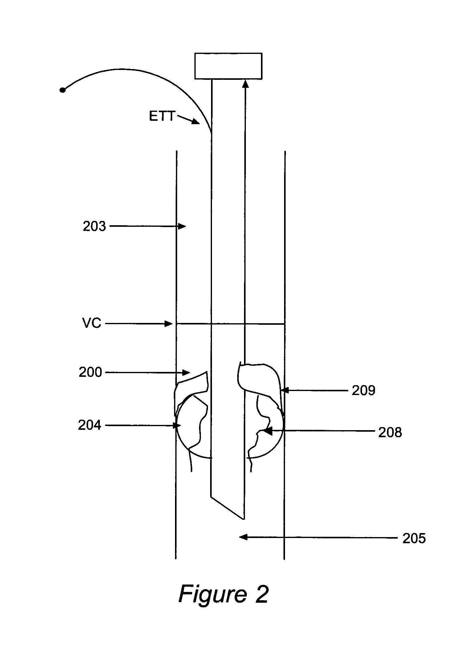
[0060]FIG. 6 shows the inventive sleeve 500 extending from below the balloon to the proximal tube when the sleeve 500 is used with a traditional endotracheal tube ETT with a pilot balloon for cuff inflation. The endotracheal tube ETT, supraglottic space 203, vocal cords VC, and subglottic space 200 in FIG. 6 are as in FIG. 2. The sleeve 500 optionally may have a se...
example 2a
[0061]FIG. 7 is a modified version of the sleeve 500 of FIG. 5, modified to include ports 709 for delivery of compounds (such as antimicrobials, anesthetics, etc.) and port 708 for injection of compounds (such as anesthetics, antimicrobials, etc.).
PUM
 Abstract
Description
Claims
Application Information