Castellated optical mounting structure

a technology of optical mounting structure and barrel, which is applied in the direction of mounting, lighting and heating equipment, instruments, etc., can solve the problems of large optical and mechanical design challenge, small and more powerful imaging equipment, and high cos

Active Publication Date: 2006-05-25
APPLE INC
View PDF14 Cites 23 Cited by
  • Summary
  • Abstract
  • Description
  • Claims
  • Application Information

AI Technical Summary

Problems solved by technology

The continuing demand for smaller and more powerful imaging apparatus, coupled with the requirement for low cost, presents a considerable challenge to optical and mechanical design.
Although very small plastic lenses can be fabricated inexpensively at high volumes, the handling, alignment, and mounting of these tiny optical components into a lens assembly using multiple components poses significant problems.
However, as is exemplified in the Spinali '516 disclosure, some approaches may prove to be too complex for low-cost, miniaturized optical systems.
Even adhesives requir...

Method used


Image

  • Castellated optical mounting structure
  • Castellated optical mounting structure
  • Castellated optical mounting structure

Examples


Embodiment Construction

[0023] The present description will be directed in particular to elements forming part of, or cooperating more directly with, apparatus in accordance with the present invention. It is to be understood that elements not specifically shown or described may take various forms well known to those skilled in the art.

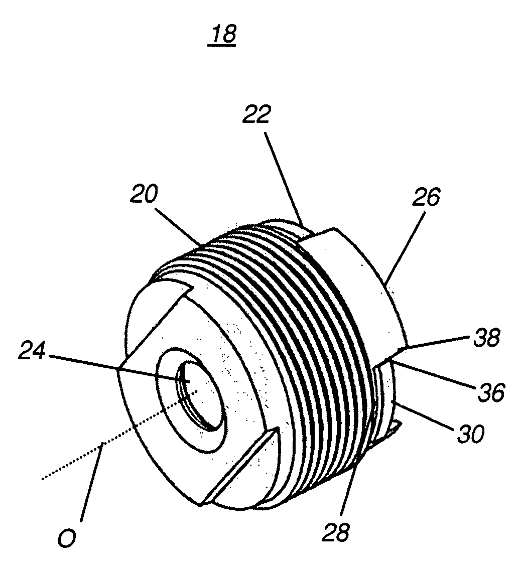
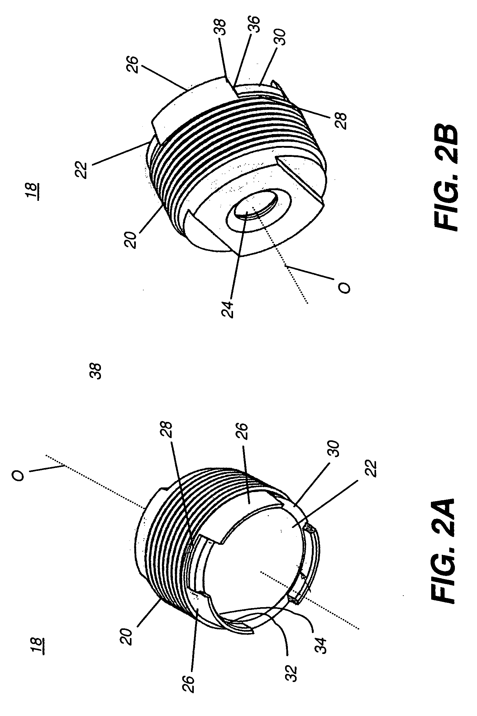
[0024] Referring to FIGS. 2A and 2B, there are shown perspective views of a lens assembly 18 with a lens barrel 20 that serves as an optical mounting structure in one embodiment for mounting optical components along an optical axis O. FIGS. 4A and 4B show side views of lens assembly 18. A lens element 22 is mounted in lens barrel 20 as an outer lens in this optical assembly, for facing a sensor circuit, for example. A second lens 24 is configured to face the object being imaged or light source, for example. Lens barrel 20 is castellated, having one or more elongated portions 26 separated by gaps 28, best shown in FIG. 4A. Elongated portions 26 extend in a direction that is g...


PUM


Abstract

An optical assembly has a lens element having a plurality of radially extending tabs and a mounting structure having a plurality of retaining members. The retaining members extend in a direction substantially parallel to an optical axis defined by the mounting structure and are positioned complementary to the radially extending tabs of the lens element. A portion of the mounting structure is in an interference fit with the a portion of the lens element.

Description

FIELD OF THE INVENTION [0001] The invention relates generally to optical component mounting and more particularly relates to a barrel mounting apparatus for a lens. BACKGROUND OF THE INVENTION [0002] The growth of portable, personal electronics devices such as cellphones, PDAs, and similar devices, has spurred development of miniaturized cameras and light-sensing components that can be incorporated into these devices. The continuing demand for smaller and more powerful imaging apparatus, coupled with the requirement for low cost, presents a considerable challenge to optical and mechanical design. Low-cost lens assemblies, typically including a number of plastic lens elements, are being used increasingly for these applications. As lenses become smaller, however, there are a number of practical considerations that are of comparatively little concern for design of larger optical systems. [0003] Although very small plastic lenses can be fabricated inexpensively at high volumes, the hand...

Claims


Application Information

Patent Timeline
IPC IPC(8): F21V17/00
CPCG02B7/022G02B7/025
Inventor SCHMIEDER, JAMES A.LUDINGTON, PAUL D.
Owner APPLE INC
Why Eureka
Try Eureka