Compound bone structure of allograft tissue with threaded fasteners

a technology of allograft tissue and bone structure, which is applied in the field of composite allograft bone devices, can solve the problems of inability to construct size, limited size, dimension and shape of cortical bone, and the limitation of plastics and metal, bone parts and bone products made from allograft cortical tissue, so as to promote bone growth

Inactive Publication Date: 2006-05-16
MUSCULOSKELETAL TRANSPLANT FOUND INC
View PDF9 Cites 100 Cited by
  • Summary
  • Abstract
  • Description
  • Claims
  • Application Information

AI Technical Summary

Benefits of technology

[0021]The compound bone structure has an exterior surface that can be shaped to form an implant that can support the anatomical load and orient the implant in the surgical site so that the anatomical load is applied to the engaged first and second mating faces in the normal direction. Complimentary mating structures formed on the first and second mating faces prevent displacement of the first bone member with respect to the second bone member in both a longitudinal direction and a transverse direction when an anatomical load is applied.

Problems solved by technology

Unfortunately because of the size limitation of the bone material only devices of a certain size could be constructed.
Cortical bone has one serious limitation that plastics and metal do not have.
Bone parts and bone products made from allograft cortical tissue are limited in size, dimension and shape because of the anatomical limits on the thickness and length of the source bone.
The length of the cortical tissue is also naturally limited by the size and the weight of the allograft tissue donor.
Shaped implants made from these other long bones are also necessarily limited in dimension.
Many medical problems and surgical procedures require implants larger than have previously been made out of allograft cortical tissue.
Second, the compound structure of the implant must hold together during the post-operative period during which the allograft tissue is resorbed and remodeled.
There are relatively few devices used in bone repair constructed of allograft bone because of the difficulty in obtaining and shaping the material and the natural limits placed on the size of the device based on the constraints of the sizes of the natural bone which can be shaped to form devices of a larger required size.
However, all of these bone structures are limited to the size and shape of the original material.
Until now, the only way that separate bone pieces could be joined together to arrive at a larger device has been to tongue and groove the respective pieces which creates shearing areas and limits the use to which such constructed device could be used.
This is a significant problem where a device is placed under stress and shearing forces as for example where it is hammered into place between vertebrae or into other bone areas.

Method used


Image

  • Compound bone structure of allograft tissue with threaded fasteners
  • Compound bone structure of allograft tissue with threaded fasteners
  • Compound bone structure of allograft tissue with threaded fasteners

Examples


Embodiment Construction

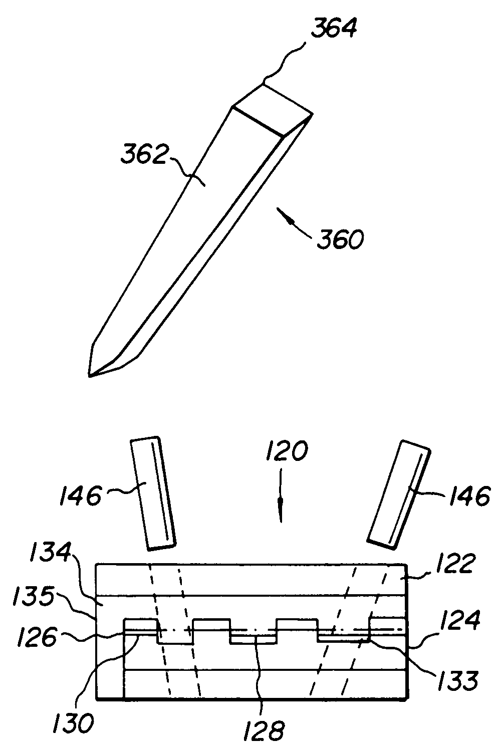
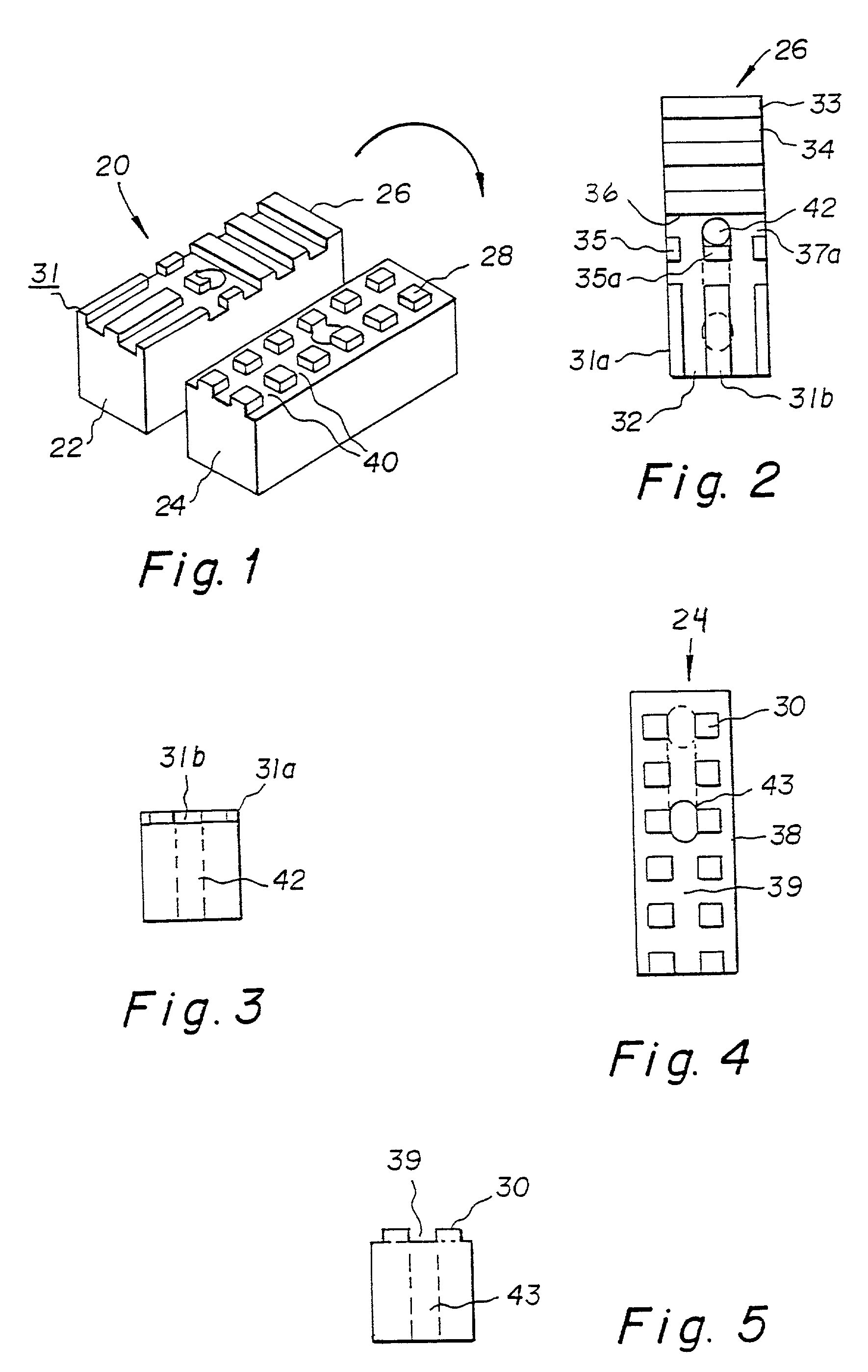
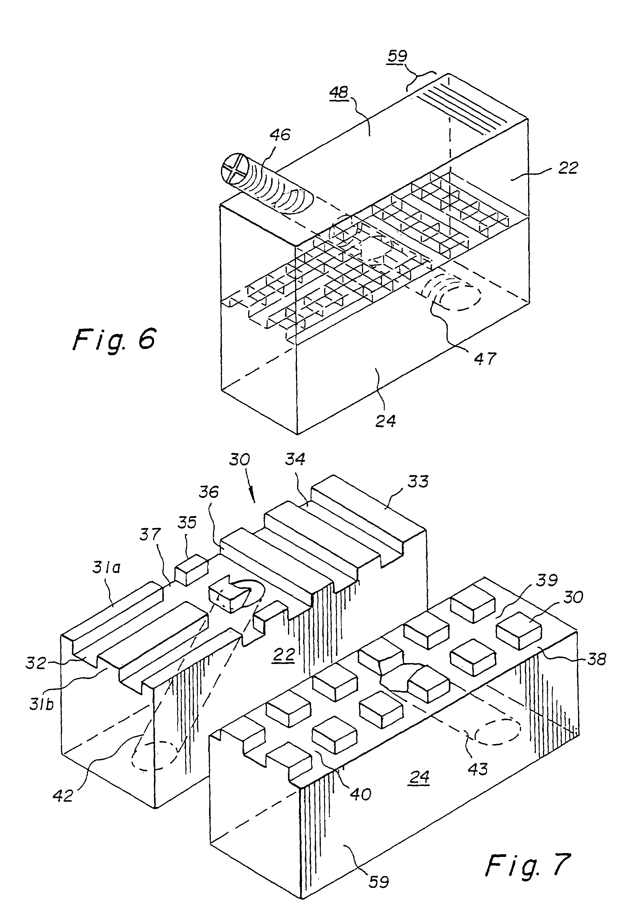
[0048]The preferred embodiment and the best mode of the invention is shown in FIGS. 1–7. FIG. 1 shows an exploded side view of a compound bone device 20 with a first bone member 22 and a second bone member 24 flipped for viewing. The first and second bone members 22, 24 are constructed from rectangular blocks of bone tissue that have been machined or shaped by other suitable means. Each bone member 22, 24 has a mating face or engagement surface 26 and 28 as shown in FIGS. 2 and 4 respectively that has been shaped to form integral mating projections or teeth 30 on each face 26, 28 so that the members 22, 24 can be engaged to form the compound bone device 20 shown in FIG. 6.

[0049]Bone member 22 has a mating face 26 constructed with three bar projections 31 separated by grooves 32 formed on one end. The bar projections 31 run parallel to the longitudinal axis of the bar member and extend along the mating face less than ½ the length of the bar member. The grooves 32 are preferably aroun...


PUM

PropertyMeasurementUnit
thicknessaaaaaaaaaa
thicknessaaaaaaaaaa
thicknessaaaaaaaaaa

Abstract

A composite allograft bone device having a first bone member body with a face that defines a plurality of spaced projections forming a pattern and a second bone member body defining a face that forms a plurality of spaced projections forming a second pattern. The projections in the first face allow the two bodies to be mated together. The mated bodies form a composite bone device which is provided with a throughgoing bore and a threaded rod member mounted in the throughgoing bore extending into and engaging the bone member bodies holding the same together. Alternatively a rod member with a demineralized or knurled outer surface can be press fit into the throughgoing bore engaging the bone member bodies in an interference fit holding the same together. In another embodiment an inner central cancellous bone block is surrounded by plates or a U shaped base constructed of cortical bone material.

Description

RELATED APPLICATIONS[0001]This is a continuation-in-part of U.S. patent application Ser. No. 09 / 196,251 filed Nov. 20, 1998 and issued into U.S. Pat. No. No. 6,025,538 on Feb. 15, 2000.BACKGROUND OF THE INVENTION[0002]1. Field of Invention[0003]The present invention generally relates to allograft bone devices for surgical implantation into bone tissue and particularly to a composite allograft bone device constructed from two or more separate bone pieces made from allograft, autograft and xenograft bone tissue that can be fastened together to have dimensions that are larger than the dimensions of naturally occurring bone suitable for implantation in a surgical site.[0004]2. Description of the Prior Art[0005]Allograft bone tissue is widely used in orthopedic, neuro-, maxillofacial, podiatric and dental surgery. Allograft tissue is valuable in these fields of surgery because it is strong and it biointegrates well over time with the recipient patient's tissue. Allograft bone tissue can ...

Claims


Application Information

Patent Timeline
Patent Type & Authority Patents(United States)
IPC IPC(8): A61F2/28A61F2/44A61F2/00A61F2/30A61L27/36
CPCA61F2/28A61F2/447A61L27/3608A61L27/365A61L2430/02A61F2/442A61F2002/2835A61F2002/2839A61F2002/30057A61F2002/30112A61F2002/30153A61F2002/30261A61F2002/30266A61F2002/30324A61F2002/30331A61F2002/30377A61F2002/3038A61F2002/30383A61F2002/30433A61F2002/30448A61F2002/30492A61F2002/30599A61F2002/30604A61F2002/30782A61F2002/30787A61F2002/30831A61F2002/30892A61F2002/30975A61F2220/0025A61F2220/0033A61F2220/0041A61F2220/005A61F2230/0004A61F2230/0019A61F2230/0082A61F2250/0036A61F2250/0063A61F2/30724A61F2002/30367
Inventor YACCARINO, III, JOSEPH A.GERTZMAN, ARTHUR A.FERRARA, RAYMOND G.
Owner MUSCULOSKELETAL TRANSPLANT FOUND INC
Why Eureka
Try Eureka