Adjustable net support system

a support system and adjustable technology, applied in tennis, sport apparatus, etc., can solve the problems of difficult to align and position the net when the poles are on, tedious net mounting process, and inability to adjust the net, so as to reduce the effective cross-sectional dimension of the net, reduce the cross-sectional dimension of the first and second sidewalls, and reduce the effect of cross-sectional dimensions

Inactive Publication Date: 2006-06-01
PADILLA RONALD G
View PDF8 Cites 11 Cited by
  • Summary
  • Abstract
  • Description
  • Claims
  • Application Information

AI Technical Summary

Benefits of technology

[0009] In one embodiment, the bracket may include at least one sleeve portion adapted to slideably receive either the support pole or the net pole as a received pole. The sleeve portion has a sidewall formed in a generally C-shaped cross-section of a selected effective cross-sectional dimension. The bracket may further be provided with a flange projecting from longitudinally extending edges of the sidewall in facing relation to one another. As such, the fastener is operative to advance the flanges toward one another thereby to reduce the effective cross-sectional dimension thereof.
[0010] In another embodiment the bracket includes a first sleeve portion having a first sidewall that is adapted to slideably receive the support pole and a second sleeve portion having a second sidewall that is adapted to slideably receive the net pole. Each of the first and second sidewalls are formed in a generally C-shaped cross-section with an effective cross-sectional dimension. Here, the first sidewall includes a pair of first flanges projecting from longitudinally extending edges thereof in facing relation to one another. The second sidewall includes a pair of second flanges projecting from longitudinally extending edges thereof in facing relation to one another. The first and second pairs of flanges engage one another and the fastener is operative to advance the flanges toward one another thereby to reduce the cross-sectional dimensions of said first and second sidewalls.
[0011] The bracket may include a pair of spaced-apart webs interconnecting respective longitudinal edges of the first and second sidewalls. Here, the fastner is operative to advance the webs toward one another thereby to reduce the cross-sectional dimensions of the first and second sidewalls.

Problems solved by technology

Some conventional net poles have fixed net attachment points on them making it difficult to align and position the net when the poles are on uneven ground.
In cases where flexible poles are used, the act of tensioning one corner of the net can cause flexure in the pole and change the tension already achieved on the opposite corner thus making the net mounting a tedious, iterative process.

Method used


Image

  • Adjustable net support system
  • Adjustable net support system
  • Adjustable net support system

Examples


first embodiment

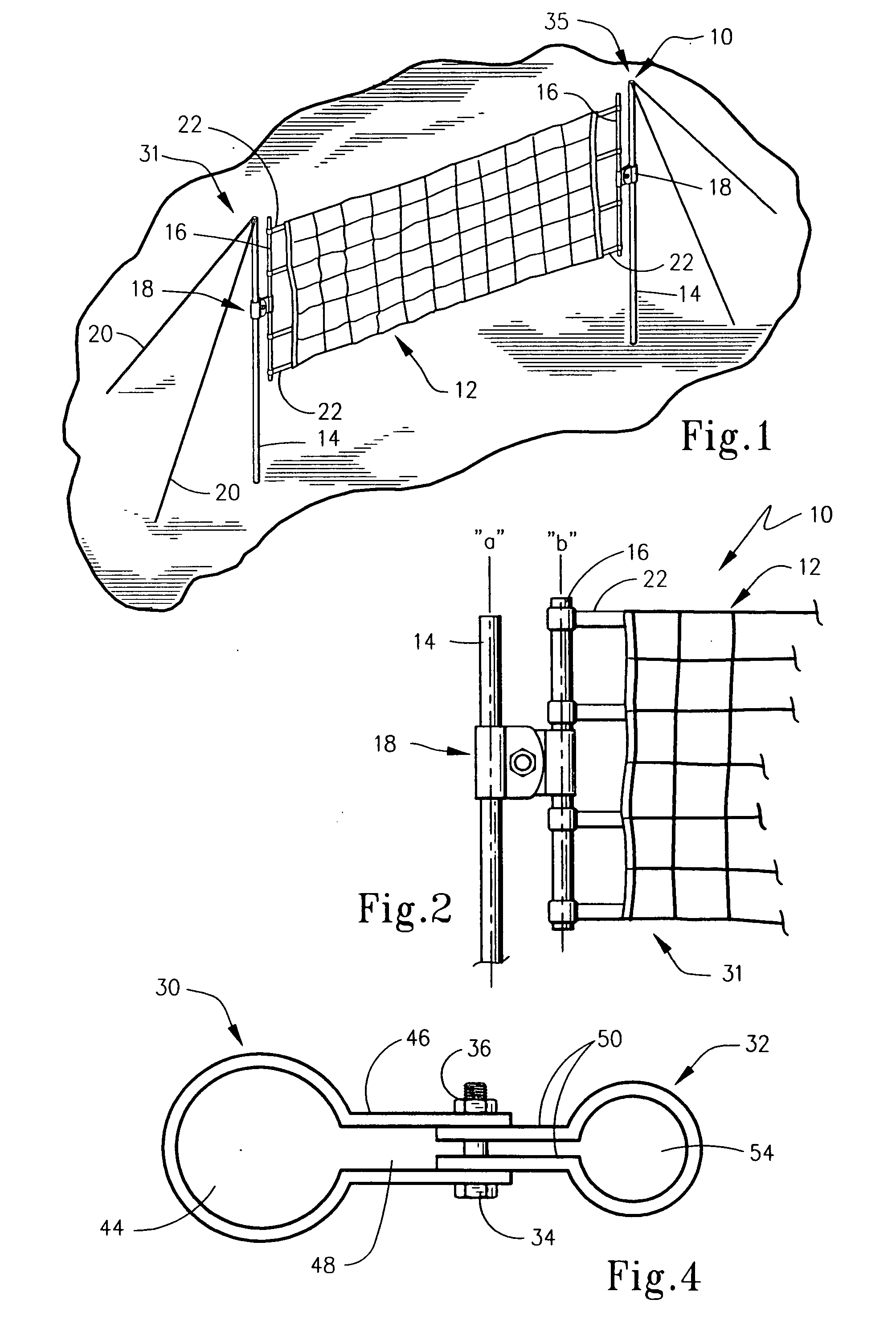
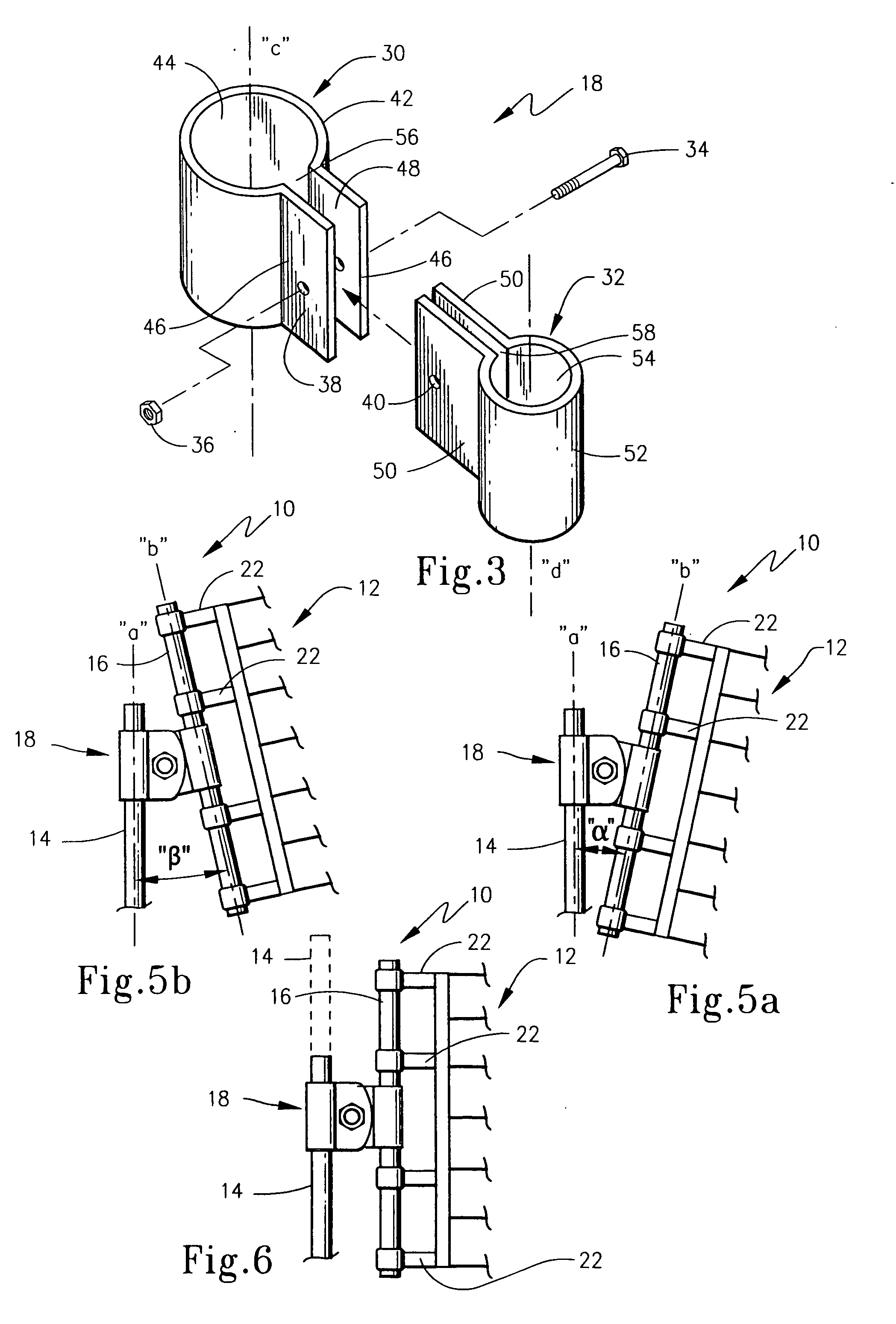
[0030] bracket 18 is shown in FIG. 3. Here bracket 18 includes a first sleeve portion 30, a second sleeve portion 32 and fastener in the form of a nut 36 and bolt 34. Both sleeve portions 30 and 32 are of a similar shape and, the first sleeve portion 30 is formed of a cylindrical tube that is generally C-shaped in cross-section with a longitudinal axis “c” and with a longitudinal slot 56, a first sleeve sidewall 42, and a cylindrical interior 44. The first sleeve portion 30 includes a pair of planar sleeve flanges 46 which are affixed to, or formed integrally with, the sleeve sidewall 42 at the longitudinal slot edges. The flanges 46 extend the length of the sleeve and also extend in an outwardly direction from axis “c” in faction relation to one another. The flanges 46 are also oriented to be generally parallel to one another and positioned to define an interior region 48 of a selected size. The flanges 46 include first sleeve holes 38.

[0031] As seen in FIGS. 3 and 4, the second sl...

third embodiment

[0037] bracket 218 is shown in FIG. 8. Here the bracket 218 includes two geometrically similar sleeves, first sleeve 230 and second sleeve 232. Each of the sleeves 230 and 232 includes a slotted pole collar 242 with a slot 234 and lobes 246. Each lobe 246 is positioned on the pole collar 242 opposite of the slot 234. Sleeve clamp posts 260 are affixed to the pole collar 242 near each of the slots 234. The collars 242 are selectively clamped to their respective pole 14 or 16 by drawing the posts 260 together thus narrowing the slot 234. One means of accomplishing this is by providing one of the posts 260 with a threaded hole 270 while the other contains a smooth bore 272. A clamp bolt 274 which includes a partially threaded shaft 266 and a thumbwheel 264 engages the threaded clamp post 260 and rotating the clamp bolt 274 draws the posts 260 together which clamps sleeve 230 or 232 to one of the poles 14 or 16. One skilled in the art can also appreciate that other means such as a bolt ...

fourth embodiment

[0039] bracket 318 is shown in FIG. 9. Here bracket 318 consists of a single longitudinally extruded piece with an “hourglass”-shaped cross-section. Bracket 318 includes a pair of spaced apart webs 331 and 335 interconnecting respective longitudinal edges of first and second sidewalls 330 and 332 that each have generally circular shaped interior regions 344 and 354 which are sized to accept support pole 14 in one and net pole 16 in the other and to allow the selectable positioning of the poles within the collar 318. The collar 318 is shaped to produce a gap 370 between the interior regions 344 and 354. A hole 372 passes through the collar and accepts a fastener such as a bolt and nut which can be engaged to draw the sides of the collar 318 or otherwise reduce the cross-sectional dimensions of first and second sidewalls 330 and 332 together to clamp the collar 318 about the poles 14 and 16. Unlike the previous embodiments, this embodiment does not allow the selectable rotation of the...


PUM


Abstract

A pole assembly supports an edge of a net by means of a support pole adapted to be positioned upright on a surface. A net pole is secured to an edge portion of the net to be suspended. A bracket connects the support pole and the net pole to one another at selected relative orientations. A fastener then secures the support pole and the net pole at the selected orientation. The selected orientation may be longitudinal positioning or angular positioning. A net system is disclosed and employs a pair of support pole and net pole combinations and a net to be suspended thereby. A method of positioning a net above a surface utilizing this structure is also disclosed.

Description

FIELD OF THE INVENTION [0001] The present invention broadly concerns a net system. More particularly, the present invention concerns a sports net system that allows for the adjustment of the sports net above the support surface and that may further accomplish a uniform tension of the net. The present invention is also directed to a method of positioning a net above a support surface. BACKGROUND OF THE INVENTION [0002] Society enjoys recreation. It is a welcome relief from work and can be a means of socialization and exercise. Playing a game of badminton or volleyball in the backyard or local park has long been a weekend pastime. A number of recreational activities including tennis, paddleball, badminton, volleyball, soccer and other such court games require a net as part of the game. The net is used to demark a boundary or to provide an interference surface for the ball or game piece. Conventional nets consist of a tensioned web of flexible material that is suspended between poles, ...

Claims


Application Information

Patent Timeline
Patent Type & Authority Applications(United States)
IPC IPC(8): A63B61/02
CPCA63B61/02
Inventor PADILLA, RONALD G.
Owner PADILLA RONALD G
Why Eureka
Try Eureka