
Intelligent configuration system for power distribution feeder reclosers and switches

a technology of intelligent configuration system and feeder, which is applied in the direction of ignition automatic control, electric controller, instruments, etc., can solve the problems of large number of potential customers, municipal utilities or co-ops, and lack of knowledge and capability to configure such sophisticated devices, and large utilities may experience similar problems

Active Publication Date: 2006-06-01
ABB RES LTD
View PDF15 Cites 56 Cited by
  • Summary
  • Abstract
  • Description
  • Claims
  • Application Information

AI Technical Summary

Benefits of technology

[0008] An exemplary control system for configuring an intelligent electronic device in a power delivery system includes a) a mechanism arranged to receive information identifying the intelligent electronic device and its capabilities, generate a configuration profile for the intelligent electronic device based on the received information, receive oper...

Problems solved by technology

However, a large number of potential customers, such as small municipal utilities or co-ops, do not have the requisite knowledge and capability to configure such sophisticated devices.
Consequently small utilities and co-ops can be reluctant to introduce more sophisticated power system applications that might improve their services.
Large utilities may experience similar problems.
Even for the larger utility customers, the range of features available for feeder automation communications and protection can be overwhelming.
Many power protection engineers do not have the necessary knowledge to properly configure the newer communication schemes now available for feeder automation.
Furthermore, many of the protection and monitoring functions are not applied, since users do not know how to set them up.
Another problem is that engineers and technicians may be unfamiliar with functionality of the intelligent electronic devices they are configuring and operating, and may underutilize capabilities of the devices.

Method used


Image

  • Intelligent configuration system for power distribution feeder reclosers and switches
  • Intelligent configuration system for power distribution feeder reclosers and switches
  • Intelligent configuration system for power distribution feeder reclosers and switches

Examples


Embodiment Construction

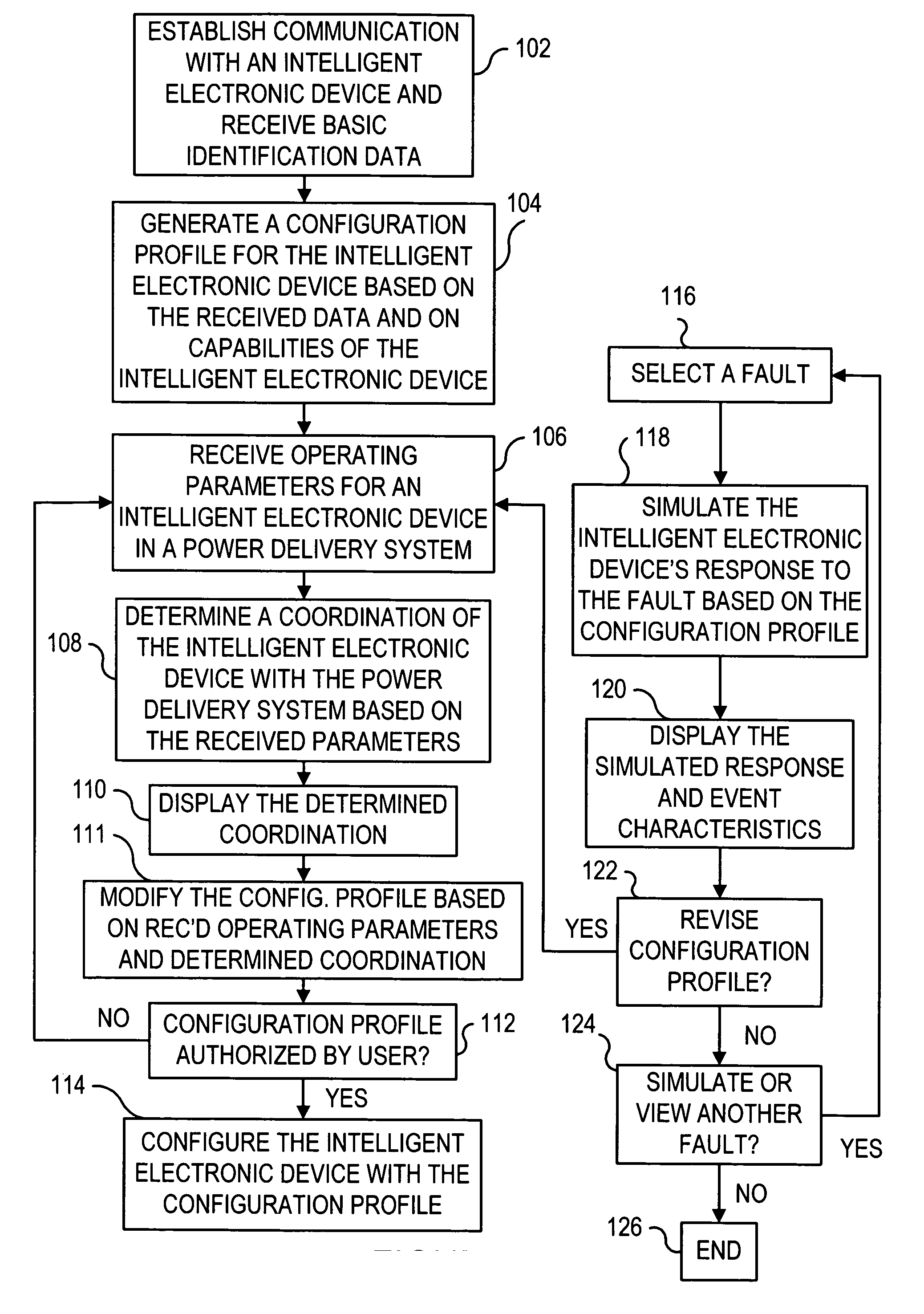
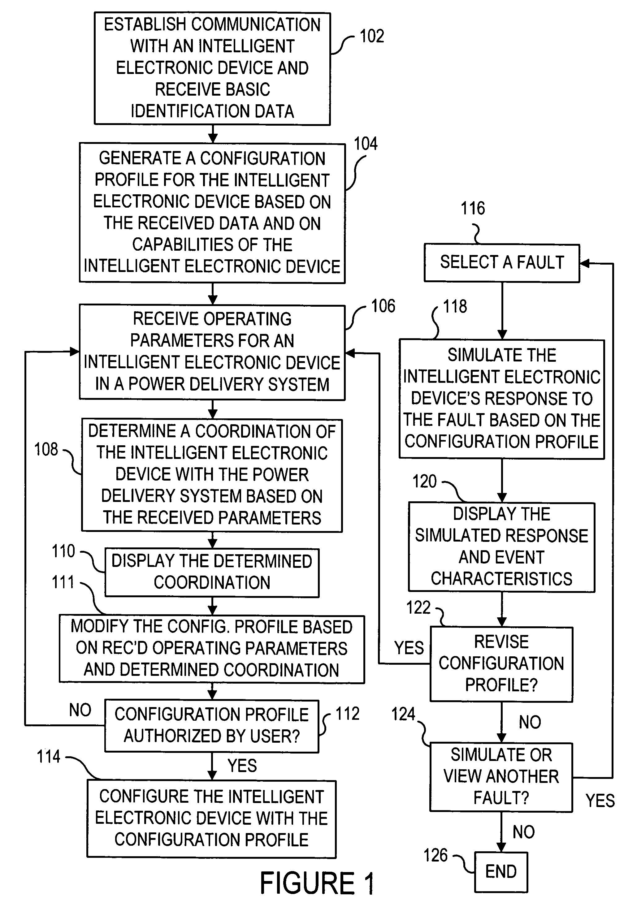
[0023]FIG. 1 illustrates operation of an exemplary intelligent configurator in accordance with an embodiment, wherein in a first step 102, communication is established with an intelligent electronic device, and basic identification data are received, for example from the intelligent electronic device. The basic identification data for the intelligent electronic device can include, for example, communication parameters, catalog number, serial number, data rate, communication protocol, and so forth.

[0024] From block 102 control proceeds to block 104, where a configuration profile for the intelligent electronic device is generated based on the received basic identification data and on capabilities of the intelligent electronic device. In an exemplary embodiment, the generated configuration profile can be a default profile.

[0025] The capabilities of the intelligent electronic device can be included with the basic identification data, and / or can be provided to the analysis tool, for ex...


PUM


Abstract

An exemplary method for configuring an intelligent electronic device in a power delivery system includes receiving identification data for the intelligent electronic device, based on the received identification data and on capabilities of the intelligent electronic device, generating a configuration profile for the intelligent electronic device, receiving operating parameters for the intelligent electronic device, determining a coordination of the intelligent electronic device with the power delivery system based on the received operating parameters, displaying the determined coordination, modifying the configuration profile based on the received operating parameters and the determined coordination, and configuring the intelligent electronic device with the modified configuration profile.

Description

RELATED APPLICATIONS [0001] U.S. application Ser. No. 10 / 699,920 and U.S. applications corresponding to ABB Inc. reference numbers B030460, B030470, B030230, and B020360 are hereby incorporated by reference.BACKGROUND INFORMATION [0002] Reclosers and switches currently used for outdoor power distribution systems include sophisticated protection and control electronics that need to be configured extensively for specific customer applications. Large utilities maintain a small number of application engineering experts that have the knowledge and expertise to configure these devices. However, a large number of potential customers, such as small municipal utilities or co-ops, do not have the requisite knowledge and capability to configure such sophisticated devices. Consequently small utilities and co-ops can be reluctant to introduce more sophisticated power system applications that might improve their services. Large utilities may experience similar problems. [0003] Even for the larger...

Claims


Application Information

Patent Timeline
IPC IPC(8): H02J13/00
CPCH02J13/001Y02E60/724Y04S10/18Y04S10/40H02J13/00001H02J2203/20H02J13/00028H02J13/00034Y02E60/00Y04S40/20
Inventor STOUPIS, JAMESCOLONNA, DONATOSCHERRER, KORNELLUBKEMAN, DAVID
Owner ABB RES LTD
Learn More