Eureka AIR delivers breakthrough ideas for toughest innovation challenges, trusted by R&D personnel around the world.

Arrangement for filling air into a rotating pneumatic tire

a technology of rotating pneumatic tires and air filling, which is applied in the direction of tires, vehicle components, transportation and packaging, etc., can solve the problems of high constructional expenditure, easy to be neglected or forgotten, and the bulge of the side wall or the bead throat is reduced, and the air sealing capacity is lost.

Inactive Publication Date: 2006-06-08
BAYERISCHE MOTOREN WERKE AG
View PDF6 Cites 28 Cited by
  • Summary
  • Abstract
  • Description
  • Claims
  • Application Information

AI Technical Summary

Benefits of technology

[0005] It is an object of the present invention to provide a simplified and nevertheless effective arrangement for filling a pneumatic tire.
[0009] As mentioned above, by means of the hose-type structure, air can be conveyed from the environment into the tire interior by means of a locally displaced squeezing of the hose-type structure, in which case a suitable valve, particularly a check valve, is provided in the transition area to the tire interior. This check valve may be a flap valve or may be formed by the conventional tire valve. In addition, the hose-type structure may be equipped with a filter, particularly a hydrophobic capillary-pore membrane filter, on the intake side toward the environment. This prevents air contaminations present in the tire area and water from being brought into the tire air or into the hose-type structure, which may cause valve leakiness, clogging, icing and corrosion or chemical attacks there.BRIEF DESCRIPTION OF THE DRAWING FIGURES

Problems solved by technology

While a simple filling by way of the valve is readily neglected or forgotten, the filling by way of controllable valves requires high expenditures because of the required lines, the sensing of the wheel load and of the pressure as well as the pertaining control.
Even the above-mentioned air pump constructions cause high constructional expenditures.
The process described above, in which, while the tire is rotating, the hose-type structure or the hose is locally squeezed having a displacing effect from the environment side toward the tire interior, will then take place only until the internal tire pressure has reached its desired value, after which, with a given load, the radial compression of the tire and thus the strength of the side wall or bead throat bulge is reduced to such an extent that the hose (or the hose-type structure) is no longer to the complete internal sealing and thus loses its air sealing capability; that is, can no longer pump or convey any additional air.

Method used


Image

  • Arrangement for filling air into a rotating pneumatic tire
  • Arrangement for filling air into a rotating pneumatic tire

Examples


Embodiment Construction

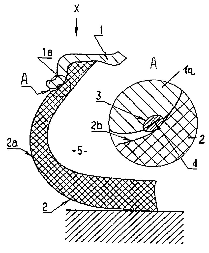
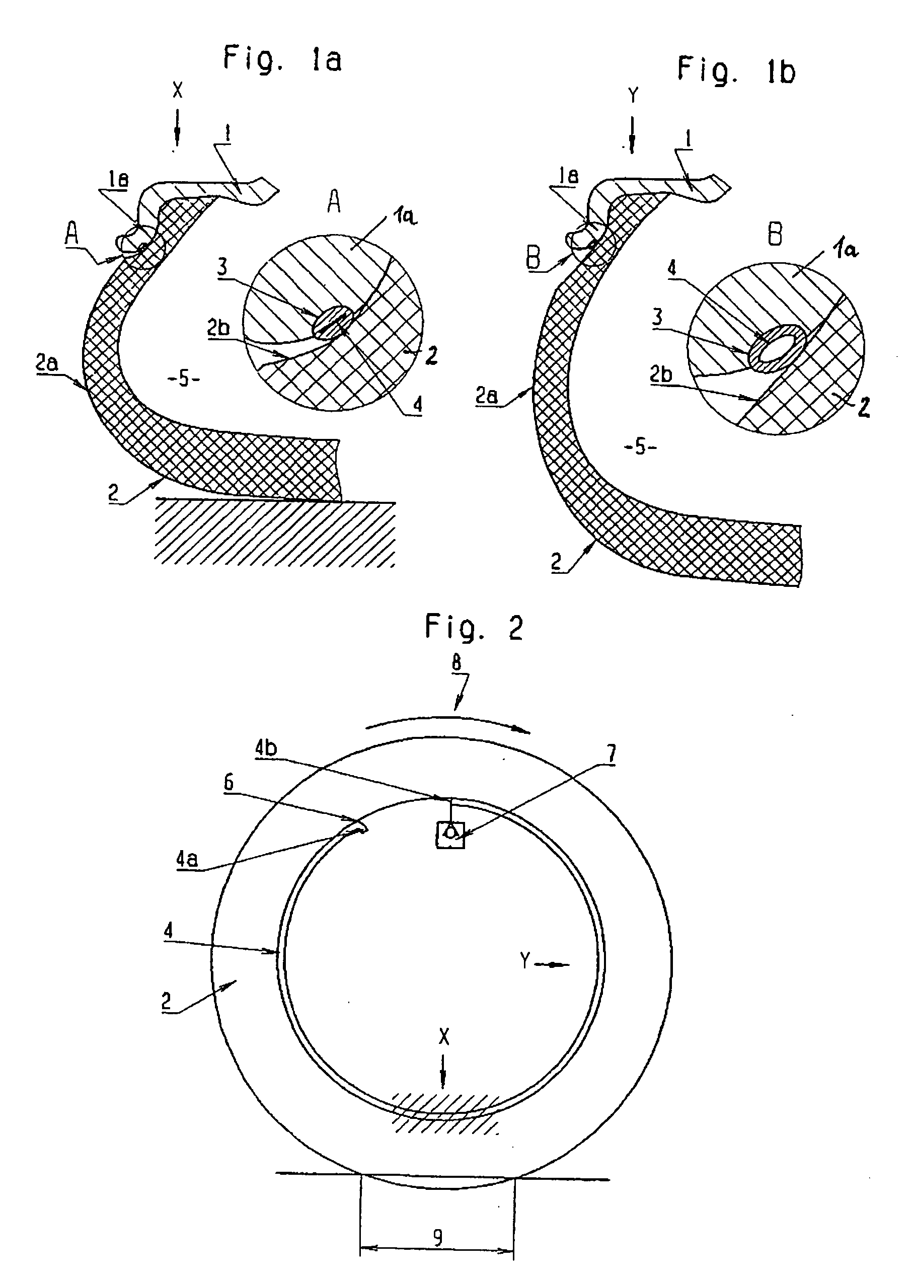
[0014] Reference number 1 indicates the rim of a vehicle wheel on which a tire 2 is mounted in a conventional manner. In the rim flange la of the rim 1, a surrounding duct 3 is provided on its surface pointing essentially in the radial direction toward the outside, in which duct 3 a hose-shaped structure 4 in the form of a hose (also reference number 4) is inserted and extends over a large portion of the circumference. The first end 4a of the hose 4 is situated in the environment, somewhere inside the rim, that is, radially within the rim well, while the second end 4b of the hose 4 by way of a check valve 7 leads finally into the tire interior or is connected with the latter. In this case, the tire 4 itself can lead into the tire interior 5 and thus radially outside the rim well. However, as an alternative, the hose 4 can also lead directly into an otherwise essentially conventional tire valve which is not shown in the figure and is provided for the regular filling of air into the t...


PUM


Abstract

A hose-type structure is arranged essentially between the tire and the rim, which structure is connected at the end side with the environment and, by way of a valve, with the interior of the tire. The hose-type structure fills the tire during its rotating movement, and is locally squeezed from the environment side toward the tire interior, in which case the hose-type structure is provided in the area between the tire and the rim flange. A duct is provided in the rim flange or in the tire in the area of its bead throat, and at least partially receives the hose-type structure in the form of a hose. The geometry of the duct and of the hose-type structure is selected such that this air-conveying squeezing essentially takes place only as long as the internal tire pressure is below a desired value.

Description

[0001] The present application is a continuation of International Application No. PCT / EP / 2004 / 051342, filed Jul. 2, 2004, and claims priority under 35 U.S.C. § 119 to German Application No. 103 35 244.9, filed Aug. 1, 2003. The entire contents of these documents are herein expressly incorporated by reference.BACKGROUND AND SUMMARY OF THE INVENTION [0002] The invention relates to an arrangement for filling air into a pneumatic tire arranged on a rim, rotating together with this rim and comprising a hose-type structure arranged essentially between the tire and the rim, which structure is connected at the end side with the environment and by way of a valve, with the interior of the tire and which, for filling the tire during its rotating movement, is locally squeezed from the environment side toward the tire interior. With respect to the technical background, reference is made to German Patent Document DE 38 81 591 T2. [0003] Normally, the pneumatic tires arranged on wheels of vehicles...

Claims


Application Information

Patent Timeline
Patent Type & Authority Applications(United States)
IPC IPC(8): B60C29/00B60C23/12
CPCB60C23/12B60C23/123B60C23/135
Inventor ELLMANN, MANFRED
Owner BAYERISCHE MOTOREN WERKE AG
Why Eureka
Eureka Blog
Learn More