Arrangement for filling air into a rotating pneumatic tire

a technology of rotating pneumatic tires and air filling, which is applied in the direction of tyre repairing, vehicle components, tire measurement, etc., can solve the problems of high constructional expenditure, easy to be neglected or forgotten, and high cost of filling by means of controllable valves, so as to reduce the strength of side walls or bead chamfer bulges and lose air sealing ability.

Inactive Publication Date: 2007-06-05
BAYERISCHE MOTOREN WERKE AG
View PDF15 Cites 107 Cited by
  • Summary
  • Abstract
  • Description
  • Claims
  • Application Information

AI Technical Summary

Benefits of technology

[0006]According to the invention, a hose-type structure, which operates as an air pump as a result of locally displaced squeezing, is provided in the area of the so-called rim flange of the rim carrying the tire. When the geometrical design or the arrangement is suitable, it can be ensured in this area in a simple manner that a rotating tire with an internal pressure which is too low in the continuously moving-along contact area, (i.e., the circumferential section in each case representing the tire contact surface), continuously squeezes the hose-type structure such that, through this hose-type structure, as desired, air is conveyed or pumped into the tire interior from an intake section connected with the environment. Because of the tire deformation taking place when the interior tire pressure is too low, this takes place in the tire side wall area adjacent to the rim flange or in the bead chamfer bulge of the tire. In this case, a corresponding tire deformation occurs already when the internal tire pressure is only to a relatively small degree below the normal desired pressure value. If, in contrast, the internal tire pressure is in the range of the desired value or above, normally no correspondingly intensive tire deformation takes place, and—as desired—no additional air is then transported through the hose-type structure into the tire interior.
[0008]In principle, it is recommended that the geometry of the duct and of the hose-type structure or of the hollow duct forming the latter be selected such, and the additional elements participating in filling air into a tire by a local squeezing of the hose-type structure be designed such that this air-conveying squeezing takes place essentially only as long as the internal tire pressure is below a desired value required for the respective current wheel load. The process described above, in which, while the tire is rotating, the hose-type structure or the hose is locally squeezed having a displacing effect from the environment side toward the tire interior, will then take place only until the internal tire pressure has reached its desired value, after which, with a given load, the radial compression of the tire and thus the strength of the side wall or bead chamfer bulge is reduced to such an extent that the hose (or the hose-type structure) is no longer to the complete internal sealing and thus loses its air sealing capability; that is, can no longer pump or convey any additional air. Thus, when the components have a corresponding design, the overall system can therefore be virtually self-governing, according to the principle of a “high-pressure self-governed compressor”.
[0009]As mentioned above, by means of the hose-type structure, air can be conveyed from the environment into the tire interior by means of a locally displaced squeezing of the hose-type structure, in which case a suitable valve, particularly a check valve, is provided in the transition area to the tire interior. This check valve may be a flap valve or may be formed by the conventional tire valve. In addition, the hose-type structure may be equipped with a filter, particularly a hydrophobic capillary-pore membrane filter, on the intake side toward the environment. This prevents air contaminations present in the tire area and water from being brought into the tire air or into the hose-type structure, which may cause valve leakiness, clogging, icing and corrosion or chemical attacks there.

Problems solved by technology

While a simple filling by way of the valve is readily neglected or forgotten, the filling by way of controllable valves requires high expenditures because of the required lines, the sensing of the wheel load and of the pressure as well as the pertaining control.
Even the above-mentioned air pump constructions cause high constructional expenditures.
The process described above, in which, while the tire is rotating, the hose-type structure or the hose is locally squeezed having a displacing effect from the environment side toward the tire interior, will then take place only until the internal tire pressure has reached its desired value, after which, with a given load, the radial compression of the tire and thus the strength of the side wall or bead chamfer bulge is reduced to such an extent that the hose (or the hose-type structure) is no longer to the complete internal sealing and thus loses its air sealing capability; that is, can no longer pump or convey any additional air.

Method used


Image

  • Arrangement for filling air into a rotating pneumatic tire
  • Arrangement for filling air into a rotating pneumatic tire

Examples


Embodiment Construction

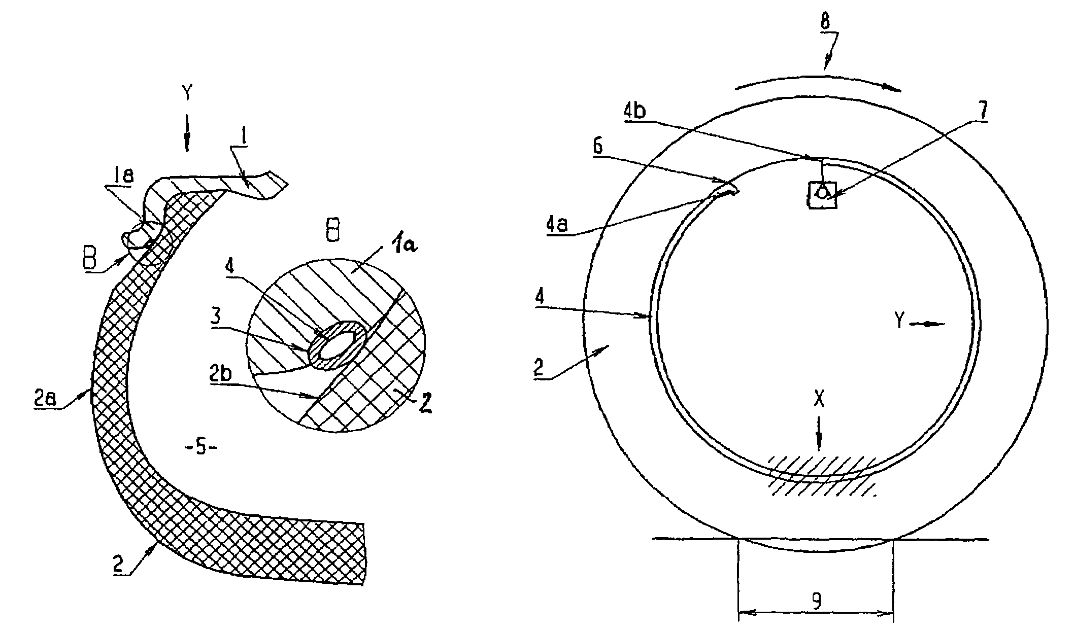
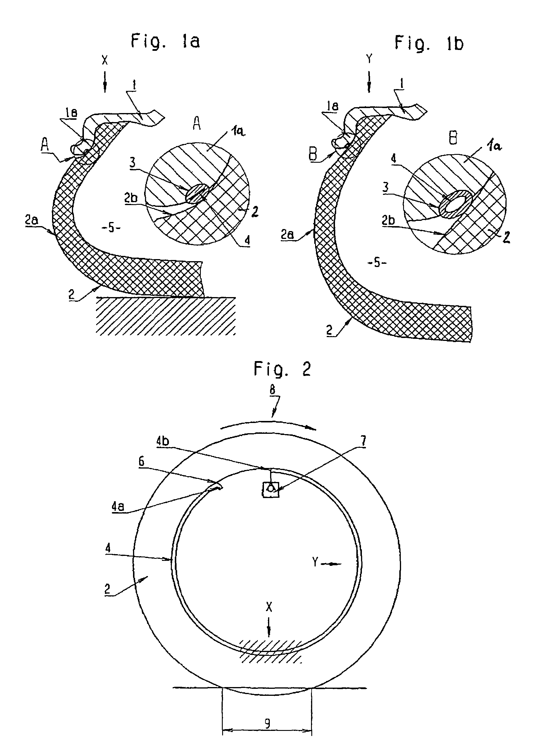
[0014]Reference number 1 indicates the rim of a vehicle wheel on which a tire 2 is mounted in a conventional manner. In the rim flange 1a of the rim 1, a surrounding duct 3 is provided on its surface pointing essentially in the radial direction toward the outside, in which duct 3 a hose-shaped structure 4 in the form of a hose (also reference number 4) is inserted and extends over a large portion of the circumference. The first end 4a of the hose 4 is situated in the environment, somewhere inside the rim, that is, radially within the rim well, while the second end 4b of the hose 4 by way of a check valve 7 leads finally into the tire interior or is connected with the latter. In this case, the tire 4 itself can lead into the tire interior 5 and thus radially outside the rim well. However, as an alternative, the hose 4 can also lead directly into an otherwise essentially conventional tire valve which is not shown in the figure and is provided for the regular filling of air into the ti...


PUM


Abstract

A hose-type structure is arranged essentially between the tire and the rim, which structure is connected at the end side with the environment and, by way of a valve, with the interior of the tire. The hose-type structure fills the tire during its rotating movement, and is locally squeezed from the environment side toward the tire interior, in which case the hose-type structure is provided in the area between the tire and the rim flange. A duct is provided in the rim flange or in the tire in the area of its bead chamfer, and at least partially receives the hose-type structure in the form of a hose. The geometry of the duct and of the hose-type structure is selected such that this air-conveying squeezing essentially takes place only as long as the internal tire pressure is below a desired value.

Description

[0001]The present application is a continuation of International Application No. PCT / EP / 2004 / 051342, filed Jul. 2, 2004, and claims priority under 35 U.S.C. § 119 to German Application No. 103 35 244.9, filed Aug. 1, 2003. The entire contents of these documents are herein expressly incorporated by reference.BACKGROUND AND SUMMARY OF THE INVENTION[0002]The invention relates to an arrangement for filling air into a pneumatic tire arranged on a rim, rotating together with this rim and comprising a hose-type structure arranged essentially between the tire and the rim, which structure is connected at the end side with the environment and by way of a valve, with the interior of the tire and which, for filling the tire during its rotating movement, is locally squeezed from the environment side toward the tire interior. With respect to the technical background, reference is made to U.S. Pat. Nos. 5,052,456 and 4,922,984.[0003]Normally, the pneumatic tires arranged on wheels of vehicles are ...

Claims


Application Information

Patent Timeline
Patent Type & Authority Patents(United States)
IPC IPC(8): B60C25/00B60C23/12
CPCB60C23/12B60C23/123B60C23/135
Inventor ELLMANN, MANFRED
Owner BAYERISCHE MOTOREN WERKE AG
Why Eureka
Try Eureka