Eureka AIR delivers breakthrough ideas for toughest innovation challenges, trusted by R&D personnel around the world.

Internal cage tube bag

Inactive Publication Date: 2007-03-08
FLOW DRY TECH INC
View PDF10 Cites 0 Cited by
  • Summary
  • Abstract
  • Description
  • Claims
  • Application Information

AI Technical Summary

Benefits of technology

[0020] It is an object of the present invention to provide a simple and cost effective desiccant package that is easy to install and remove from an integrated condenser dryer chamber of a mobile air conditioning system. As described herein, the present invention provides an Internal Cage Tube Bag (ICTB) design that is relatively easy to manufacture and that satisfies packaging and performance requirements while holding the desiccant material tightly inside the container.
[0021] The present ICTB design, which utilizes the desiccant bag itself as the package for the desiccant material, is an economical method of containing the desiccant material both before and after assembly into the condenser dryer. The ICTB design utilizes a simple internal cage component that is inserted into the desiccant bag. This design is advantageous because the internal cage component may be manufactured very inexpensively, for example molded from plastic material, and because the component may be formed to varying lengths to adapt to the customer requirements for the length of the condenser / dryer chamber.
[0023] It is another object of the invention to position the desiccant package such that the bag area on the inlet side of the condenser dryer chamber is much greater than the diameter of the integrated condenser tube, thereby greatly improving filtration performance. Since the fluid or gas flow must flow into the bag at one end and out of the bag at the other end, the invention provides two surface areas for filtration to occur. Thus, the invention provides a “double” filtration system, providing enhanced filtration capacity over other prior art devices.
[0025] Accordingly, it is another object of the present invention to configure the internal cage component in shape and size so that the sealing component can be positioned properly between the inlet and outlet tubes of the integrated condenser dryer. Proper positioning of the sealing component between the inlet and outlet tubes ensures that the inlet and outlet tubes will not be blocked by the internal cage component and that no (unfiltered) bypass of fluid outside the desiccant package is allowed.
[0027] It is yet another object of the invention to provide a sealing section that can be inexpensively constructed of nylon, temperature resistant plastic, stainless steel or aluminum, so that the sealing section can hold its dimensions throughout any heat cycle testing that could cause other materials to shrink and lose their sealing capability.

Problems solved by technology

Other methods of sealing are expensive and can be dislodged out of position.

Method used


Image

  • Internal cage tube bag
  • Internal cage tube bag
  • Internal cage tube bag

Examples


Embodiment Construction

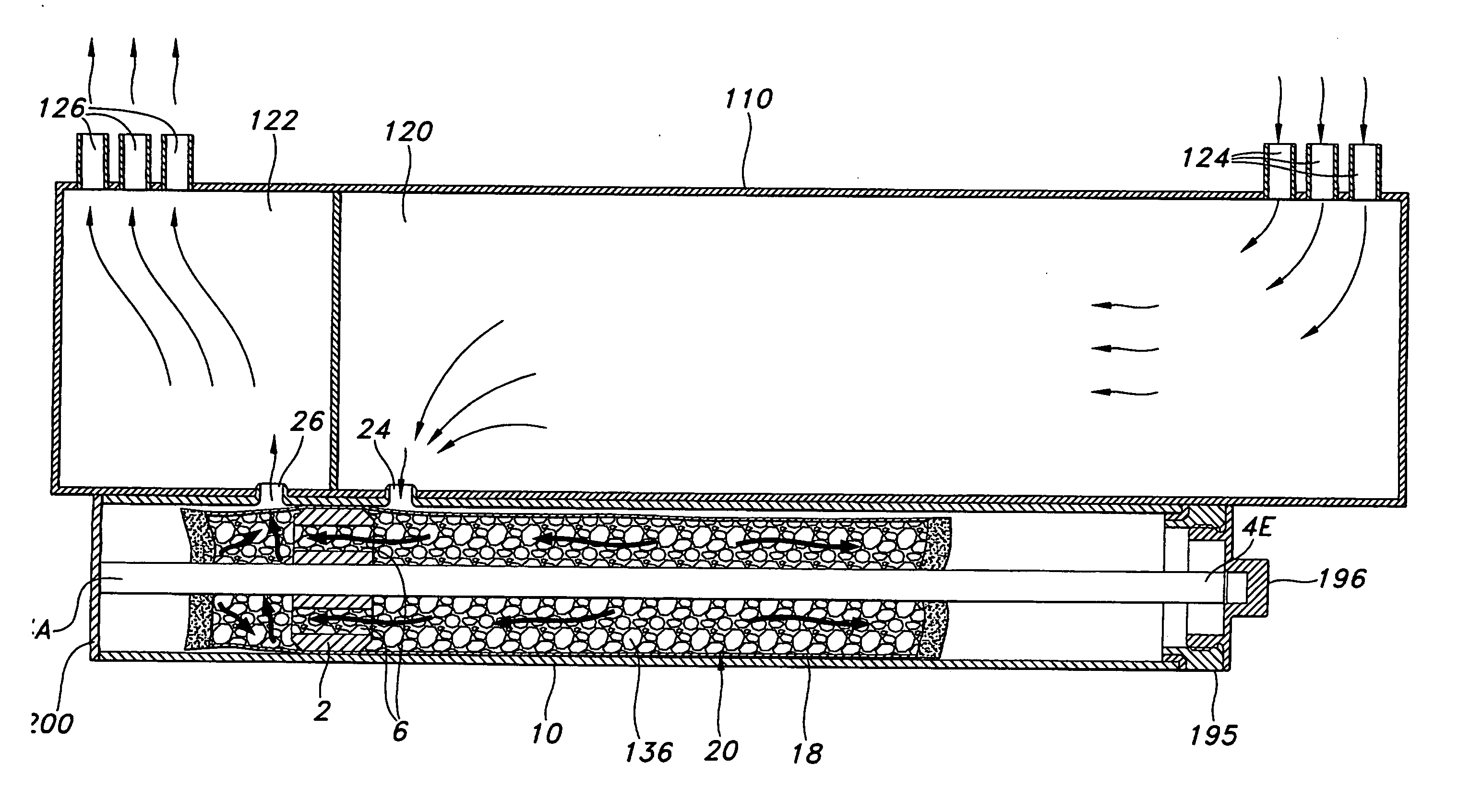
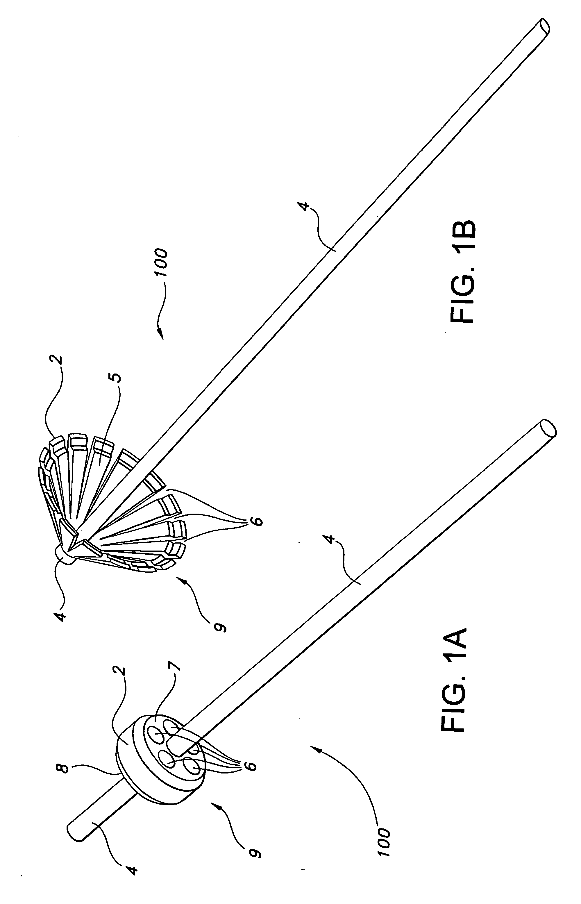
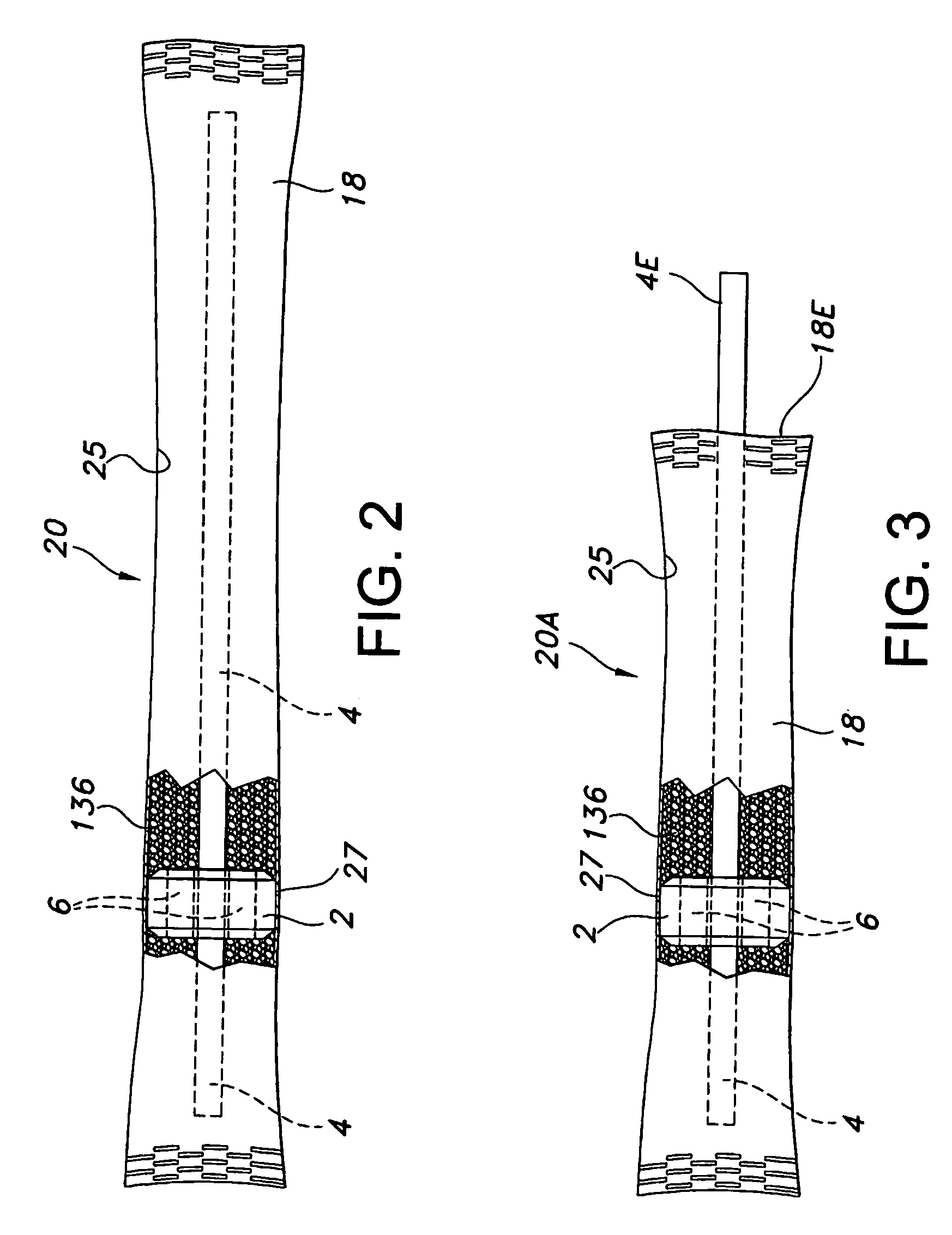
[0033] With reference now to the drawings, wherein like numerals represent like parts throughout, FIG. 1A shows an internal cage component 100 in accordance with an embodiment of the present invention. The cage component 100 comprises a base unit 9 and a center stabilizer section 4 wherein the base unit 9 further comprises a sealing section 2. According to the embodiment of FIG. 1A, the center stabilizer section 4 extends axially from a pair of side portions 7, 8 of the base unit 9 (side portion 8 not visible in FIG. 1A). The side portions 7, 8 define a passable section with a plurality of passages 6, each passage 6 preferably oriented in a circular array positioned around the outside diameter of the center stabilizer section 4 as best shown in FIG. 1A. Each passage 6 passes through the entire length of the base unit 9, thereby providing a passable section through the base unit 9 wherein a plurality of uninterrupted fluid passageways are provided between the associated side portions...


PUM


Abstract

A desiccant package for insertion into an integrated condenser dryer chamber of an air conditioning unit. The desiccant package includes an internal cage component which is enclosed inside a porous desiccant-containing bag. The internal cage component comprises an enlarged diameter base unit and sealing section to seal and support the desiccant package inside the dryer chamber. The desiccant package can be inserted into the condenser dryer at initial assembly of the air conditioning unit or as a replacement item when the original desiccant is fully saturated.

Description

CROSS-REFERENCE TO RELATED APPLICATION [0001] This application claims the benefit of U.S. Provisional Patent Application Ser. No. 60 / 471,692 filed May 19, 2003.BACKGROUND OF THE INVENTION [0002] 1. Field of the Invention [0003] The present invention relates to a desiccant-containing package for use in an integrated condenser dryer, and more particularly relates to an improved desiccant-containing package for insertion into an integrated condenser dryer chamber of a vehicle or mobile air conditioning system. [0004] 2. Description of the Prior Art [0005] Mobile air conditioning systems typically include an integrated condenser dryer chamber or receiver chamber that serves as an accumulator reservoir for refrigerant. The dryer chamber provides a convenient location for a container or package of desiccant material, usually a bag or pouch of mesh material, which absorbs water vapor from the liquid refrigerant reservoir. The desiccant bag performs better when the bag is suspended within t...

Claims


Application Information

Patent Timeline
IPC IPC(8): F25B43/00B65DF25B39/04
CPCF25B43/003F25B2339/0443F25B2339/0441
Inventor PERRINE, GLENN D.LECONEY, DOUGLAS E.
Owner FLOW DRY TECH INC
Why Eureka
Eureka Blog
Learn More