Unlock instant, AI-driven research and patent intelligence for your innovation.

Mode S transponder transmission signal decoder and Mode S transponder transmission signal decoding method

Active Publication Date: 2006-06-08
KK TOSHIBA
View PDF5 Cites 12 Cited by
  • Summary
  • Abstract
  • Description
  • Claims
  • Application Information

AI Technical Summary

Benefits of technology

[0027] Hence, it is made possible to accurately d

Problems solved by technology

Hence, it becomes impossible to correctly decode the Mode S transponder transmission signal.
A pulse of the associated wave is misidentified so as not to meet the lower limit value of the above-described predeterm

Method used


Image

  • Mode S transponder transmission signal decoder and Mode S transponder transmission signal decoding method
  • Mode S transponder transmission signal decoder and Mode S transponder transmission signal decoding method
  • Mode S transponder transmission signal decoder and Mode S transponder transmission signal decoding method

Examples


first embodiment

[0044]FIG. 4 is a configuration view of a secondary surveillance radar (SSR) system 1 according to the present invention.

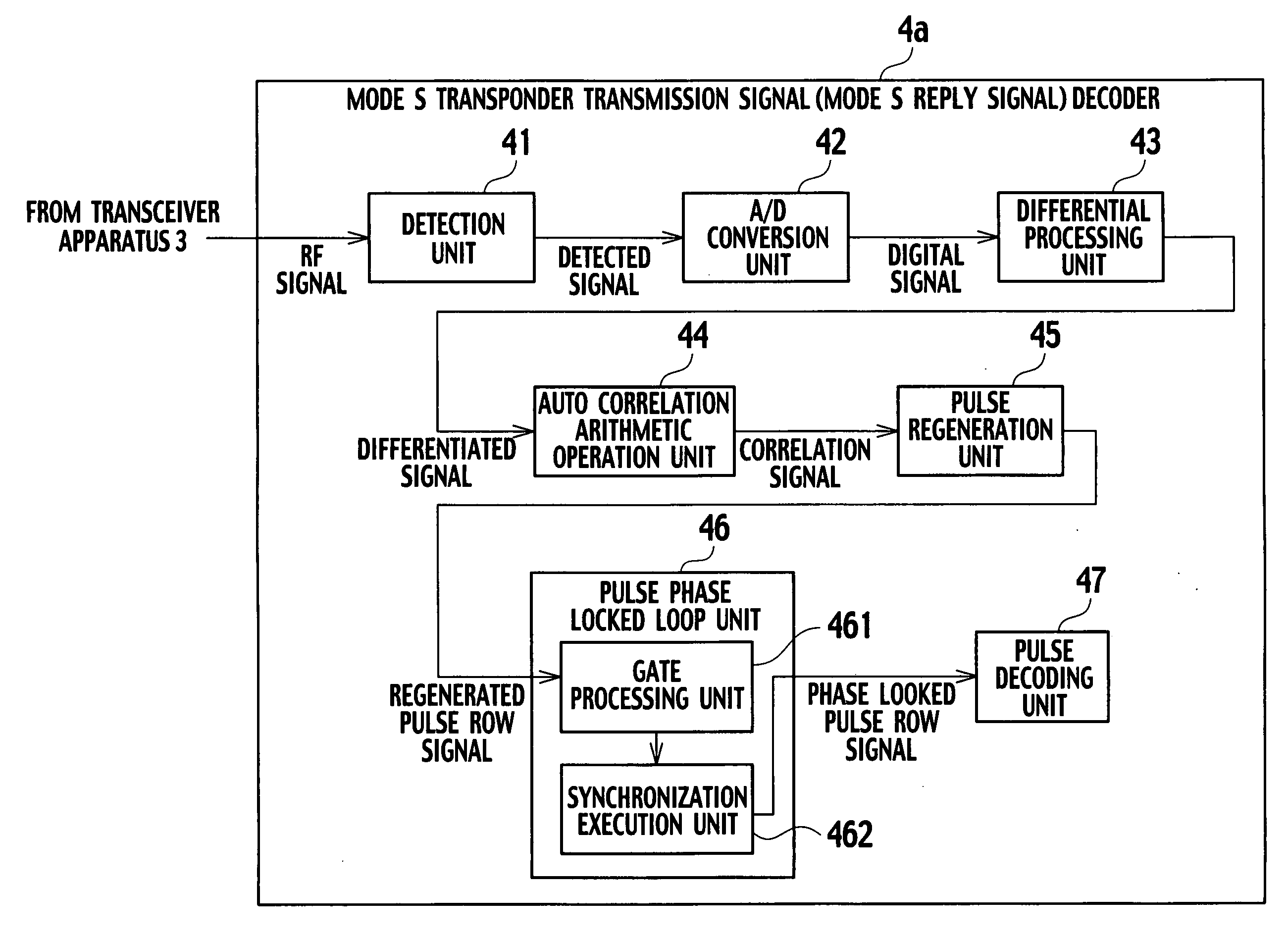
[0045] The SSR system 1 is composed of a radar antenna apparatus 2 including a ground-based radar antenna rotatable at 360° in the horizontal direction, a transceiver apparatus 3, a Mode S transponder transmission signal decoder 4a, and a transponder (Mode S transponder) 6 mounted on an aircraft 5.

[0046] The transceiver apparatus 3 transmits a Mode S interrogation signal 7 to the transponder 6 through the radar antenna apparatus 2, and the transponder 6 which has received the Mode S interrogation signal 7 transmits a Mode S reply signal 8 to the received Mode S interrogation signal. The Mode S reply signal 8 is received by the radar antenna apparatus 2 and the transceiver apparatus 3, and is decoded by the Mode S transponder transmission signal decoder 4a. Specifically, the Mode S transponder transmission signal decoder 4a functions as a Mode S reply signal decod...

second embodiment

[0063]FIG. 10 is a configuration diagram of a Mode S transponder transmission signal decoder (Mode S reply signal decoder) 4b according to the present invention.

[0064] The Mode S transponder transmission signal decoder 4b is one, in which a change is added to the above-described Mode S transponder transmission signal decoder 4a, and a pattern selection unit 48 and a pulse position synchronization unit 49 are provided instead of the pulse phase locked loop unit 46.

[0065] A repetition pattern of the pulse of the Mode S signal is predetermined, and is any one of patterns shown in FIGS. 11A to 11D.

[0066] The above-described pattern selection unit 48 selects a pattern of the pulse, which most closely resembles a pattern of the regenerated pulse row, from these patterns of the pulses.

[0067] The pulse position synchronization unit 49 performs pulse position synchronization processing based on the selected pattern of the pulse.

[0068] Note that, in the case of performing the above-descri...

third embodiment

[0076]FIG. 13 is a configuration view of an ADS-B system 9 according to the present invention.

[0077] The ADS-B system 9 is composed of the transponders 6, antennas 61, receiver apparatuses 62, and the Mode S transponder transmission signal decoders 4a or 4b, which are mounted on the aircrafts 5 (two aircrafts 5a and 5b in this drawing), a ground-based omni antenna 10, a receiver apparatus 11, and the Mode S transponder transmission signal decoder 4a or 4b.

[0078] Specifically, in the ADS-B system 9 of this embodiment, the Mode S transponder transmission signal decoders 4a or 4b are provided not only on the ground but also in the aircrafts 5a and 5b.

[0079] Note that the Mode S transponder transmission signal decoders 4a or 4b of the above-described aircrafts 5a and 5b can be disposed at arbitrary positions in the aircrafts.

[0080] Each of the transponders 6 automatically transmits a Mode S squitter signal (including the Mode S short squitter signal and the Mode S extended squitter s...


PUM


Abstract

There are provided a differential processing unit which performs differential processing for a Mode S transponder transmission signal, an auto correlation arithmetic operation unit which performs an arithmetic operation of a degree of auto correlation between an increasing change rate and decreasing change rate of a power level in the signal which has been subjected to the differential processing, a pulse regeneration unit which regenerates a pulse based on the degree of auto correlation, which has been obtained by the auto correlation arithmetic operation processing, a pulse phase locked loop unit which performs gate processing and phase locked processing for the regenerated pulse, and a pulse decoding unit which decodes the Mode S transponder transmission signal based on the pulse which has been subjected to the gate processing and the phase locked processing.

Description

CROSS-REFERENCE TO RELATED ART [0001] This application is based upon and claims the benefit of priority from the prior Japanese Application No. 2004-351163, filed on Dec. 3, 20004; the entire contents of which are incorporated herein by reference. BACKGROUND OF THE INVENTION [0002] 1. Field of the Invention [0003] The present invention relates to a Mode S transponder transmission signal decoder and a Mode S transponder transmission signal decoding method for decoding a Mode S reply signal to a Mode S interrogation signal transmitted to a transponder mounted on an aircraft, and a decoding Mode S squitter signal (including a Mode S short squitter signal and a Mode S extended squitter signal) transmitted by the transponder. [0004] 2. Description of the Related Art [0005] An aircraft surveillance radar for use in air traffic control is broadly divided into a primary surveillance radar (PSR) and a secondary surveillance radar (SSR). [0006] The above-described PSR emits radio waves from t...

Claims


Application Information

Patent Timeline
IPC IPC(8): G01S13/76
CPCG01S13/765G01S13/784H04B7/18506
Inventor OOTOMO, HISASHIAOKI, YOSHIROUKUJI, YOSHINORI
Owner KK TOSHIBA