Sternum closure device

Inactive Publication Date: 2006-06-08
AESCULAP AG
View PDF16 Cites 173 Cited by
  • Summary
  • Abstract
  • Description
  • Claims
  • Application Information

AI Technical Summary

Benefits of technology

[0014] It is advantageous for the second contact element to carry at least one elastic tongue which rests against the clamping element and enables displacement of the contact element relative to the clamping element in one direction only. The second contact element can thus be readily displaced along the clamping elemen

Problems solved by technology

However, they may also be relatively large recesses, it only being essential that the fixing projections provide

Method used


Image

  • Sternum closure device
  • Sternum closure device
  • Sternum closure device

Examples


Embodiment Construction

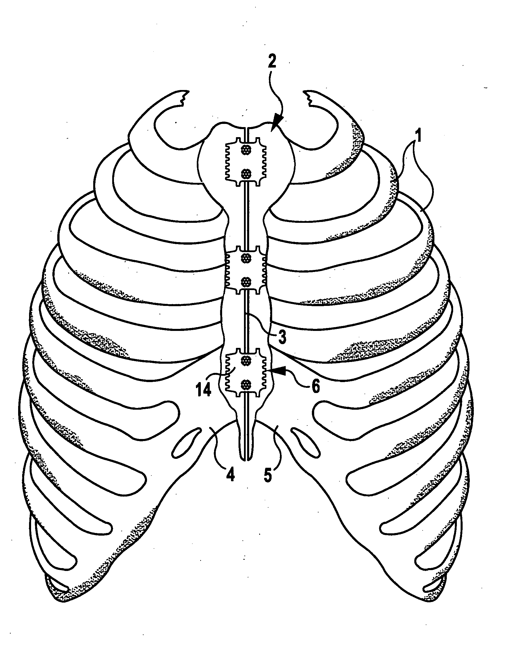
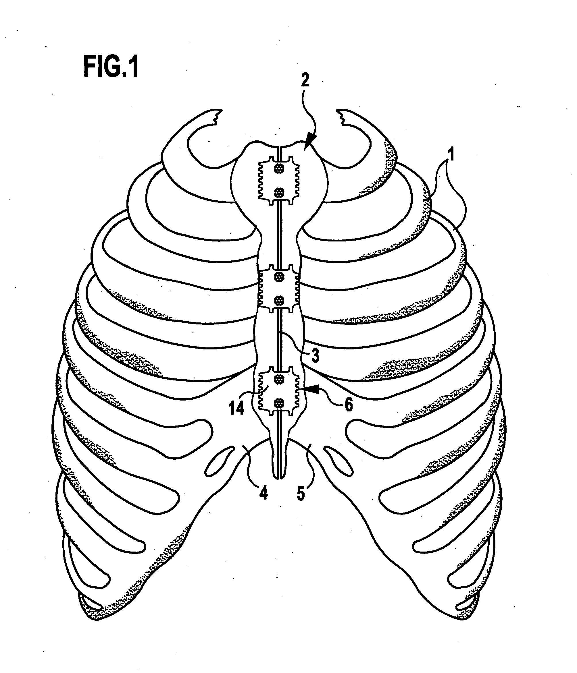
[0024]FIG. 1 shows the rib arches 1 of a patient. These are divided along the sternum 2 by a separating cut 3 in order to thereby gain access to the chest cavity. When the operation has been carried out, the two sternum portions 4, must be joined along the separating cut 3. To this end, the two sternum portions 4, 5 are pressed against each other by a tool, not shown in the drawings, for example, by means of fixation forceps, and must be fixed relative to each other in this position.

[0025] This fixing is carried out by means of sternum closure devices 6 arranged in spaced relation to one another. Three such sternum closure devices are used in the illustrated embodiment.

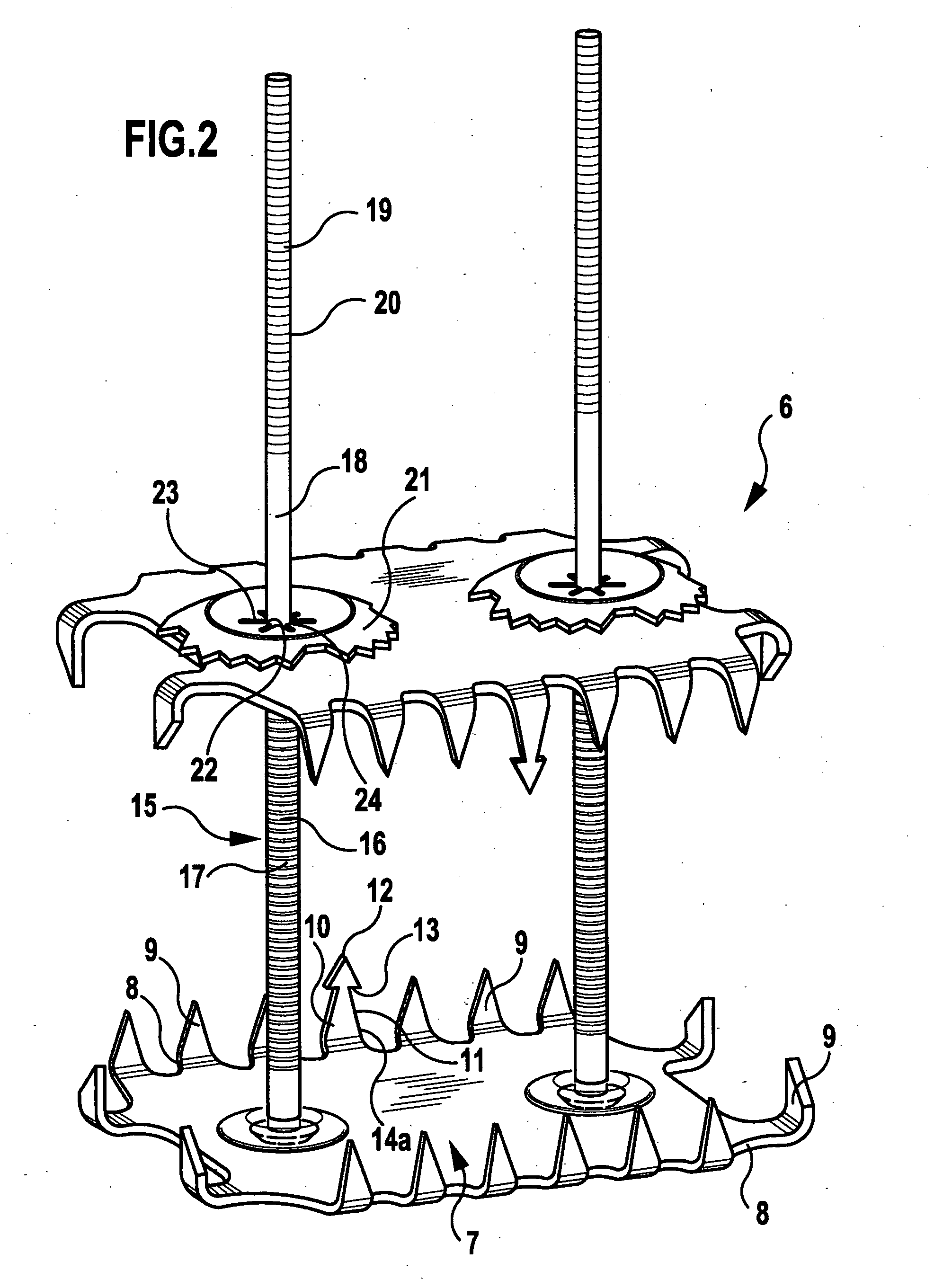
[0026] Each sternum closure device 6 is of identical design, which will be explained hereinbelow with reference to FIGS. 2 to 4.

[0027] The sternum closure device 6 comprises a rectangular, plate-shaped first contact element 7 with arms 8 protruding from it in all directions. At their free ends, the arms 8 are bent ...


PUM


Abstract

In a sternum closure device for fixing two sternum portions to be joined to each other, comprising a first plate-shaped contact element for placement against the inner surface of the sternum, a clamping element fixed on and protruding transversely from the first contact element, a second plate-shaped contact element for placement against the outer side of the sternum, the second contact element being clampable against the first contact element by means of the clamping element passing through the space between the sternum portions, and fixing projections on the first contact element pointing in the direction towards the second contact element, in order to facilitate placement of the sternum closure device, it is proposed that at least one fixing projection on the first contact element be provided with barb-shaped recesses.

Description

[0001] This application is a continuation of international application number PCT / EP2004 / 005918 of Jun. 2, 2004. [0002] The present disclosure relates to the subject matter disclosed in international application number PCT / EP2004 / 005918 of Jun. 2, 2004 and German application number 103 26 690.9 of Jun. 4, 2003, which are incorporated herein by reference in their entirety and for all purposes.BACKGROUND OF THE INVENTION [0003] The invention relates to a sternum closure device for fixing two sternum portions to be joined to each other, comprising a first plate-shaped contact element for placement against the inner surface of the sternum, at least one clamping element fixed on and protruding transversely from the first contact element, a second plate-shaped contact element for placement against the outer side of the sternum, the second contact element being clampable against the first contact element by means of the clamping element passing through the space between the sternum portion...

Claims


Application Information

Patent Timeline
IPC IPC(8): A61B17/58A61B17/00A61B17/68A61B17/80A61B17/82
CPCA61B17/688A61B17/8076A61B17/809A61B17/823A61B2017/00004
Inventor MORALES, PEDRODWORSCHAK, MANFREDEIJSMAN, LEON
Owner AESCULAP AG
Why Eureka
Try Eureka