High performance multimode horn for communications and tracking

a multi-mode, high-performance technology, applied in the field of horns, can solve the problems of degrading gain performance, affecting the performance of such antennas, and the host of challenging antenna design problems, and achieve the effect of optimal gain and efficient propagation

Inactive Publication Date: 2006-06-15
AMYOTTE ERIC +3
View PDF7 Cites 30 Cited by
  • Summary
  • Abstract
  • Description
  • Claims
  • Application Information

AI Technical Summary

Benefits of technology

[0027] An advantage of the present invention is that the multimode horn has a series of discontinuities that are designed to simultaneously propagate higher order symmetrical modes for a communications signal transmitted and / or received there through and asymmetrical tracking modes that can be used to track an incoming signal, a radio-frequency beacon tracking signal or the like by allowing the propagation of one or more tracking modes.
[0028] Another advantage of the present invention is that the multimode horn alters the symmetrical mode content of the communications signal and allow the propagation of asymmetrical mode content of the tracking signal transmitted and / or received there through via regular and / or irregular corrugation, smooth profile, choke and / or step discontinuities.
[0029] A further advantage of the present invention is that the multimode horn efficiently propagates an asymmetrical tracking mode content that can be used to track an incoming signal.
[0030] Another advantage of the present invention is that the multimode horn feeding an antenna is tailored relative to a plurality of performance parameters including at least one of the following: horn on-axis directivity, horn pattern beamwidth, antenna illumination edge-taper, antenna illumination profile, antenna spill-over losses and tracking mode return loss.
[0031] Still a further advantage of the present invention is that the multimode communications and tracking horn, when coupled to the appropriate mode extractor, is able to detect the location of an incoming signal, such as a ground beacon or the like, using a higher order asymmetrical mode content while providing an optimal gain for the communications signals over the same geographical location.

Problems solved by technology

Modern broadband high capacity satellite communication systems give rise to a host of challenging antenna design problems.
The performance of such antennas is limited by the ability to efficiently illuminate the antenna aperture with small, closely-packed feed elements producing a relatively broad primary pattern.
The main factors limiting antenna performance include: 1-High antenna spill-over losses, degrading gain performance; and 2-Limited edge illumination taper, leading to relatively high sidelobe levels.
Although multiple apertures significantly improve antenna performance by increasing the physical element size, it can be easily demonstrated that even with four apertures, the performance of MBAs employing a single feed element per beam is still limited by the aperture efficiency η of the feed element defined as:
This increase in reflector size results in a second-order increase in reflector edge-taper.
Although conical horns offer reasonable aperture efficiency (typically between 80% and 83%), they suffer from bad pattern symmetry and poor cross-polar performance.
Corrugated horns can operate over a wider band but yield an even lower efficiency, due to the presence of the aperture corrugations that limit their electrical diameter to about λ / 2 less than their physical dimension.
Consequently, as shown in FIG. 3, conventional dual-mode or hybrid mode feedhorns do not allow to achieve an optimal MBA performance, since insufficient reflector edge-taper results in high sidelobe levels and a gain degraded by high spill-over losses.
The very high gain required in multi-beam, broadband antenna systems result in very narrow pencil beams.
In many instances it is not possible to use a dedicated feed or feed cluster for antenna RF tracking purposes.
There is simply not enough room in between the communications feeds to fit the tracking feed even if the coverage zone is produced with multiple reflectors to increase the feed separation in the feed block.
There is however a significant technical challenge in matching the impedance of the multimode horn for the communications signals and the asymmetrical tracking modes over the specified frequency band(s).
Existing tracking feed chains can not support high efficiency multimode communications signals such as those described above.

Method used


Image

  • High performance multimode horn for communications and tracking
  • High performance multimode horn for communications and tracking
  • High performance multimode horn for communications and tracking

Examples


Embodiment Construction

[0052] With reference to the annexed drawings the preferred embodiments of the present invention will be herein described for indicative purpose and by no means as of limitation.

High Performance Multimode Horn for Communications and Tracking

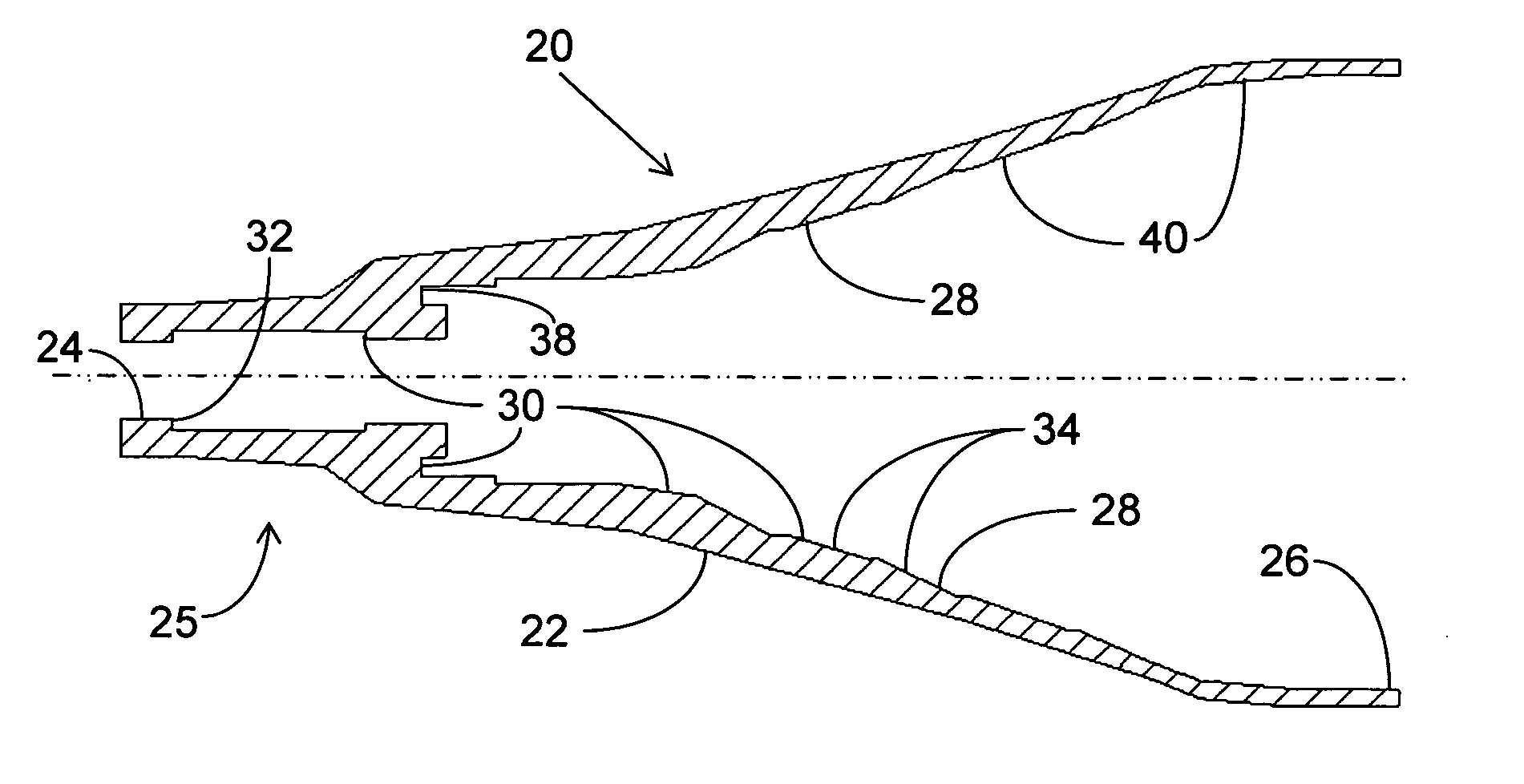
[0053] In order to overcome the performance limitations obtained with conventional feed elements, we have developed a high performance multimode horn that generates an optimal mode mix for the communications signals and propagates tracking mode signals, which can be used to accurately track a ground beacon and thus greatly reduce the performance degradations caused by pointing error. These high performance multimode horns can be used in single-aperture multibeam antennas or combined with multiple aperture antennas to further improve their RF (Radio Frequency) performance. This feed element can achieve higher aperture efficiency than conventional dual-mode or hybrid multimode solutions, while maintaining good pattern symmetry and cross-polar pe...


PUM


Abstract

A multimode horn used to feed an antenna includes a generally tapered wall for transmitting and / or receiving an electromagnetic signal there through. The wall flares radially outwardly from a throat section to an aperture and defines an internal surface having a plurality of discontinuities. The geometry of the discontinuities are configured and sized to alter the dominant mode, which conveys the communications signal, into a higher order symmetrical mode content to achieve a balance between a plurality of communications performance parameters of the antenna over a pre-determined frequency range of the signal. The discontinuities are also designed to match the horn impedance for the modes of the communications signal and for an asymmetrical mode content of a simultaneously propagating tracking signal.

Description

CROSS-REFERENCE TO RELATED APPLICATION [0001] Priority of U.S. Provisional Application No. 60 / 635,474, filed on Dec. 14, 2004, is hereby claimed.FIELD OF THE INVENTION [0002] The present invention relates to a horn for use in RF signal transmitters and / or receivers, and more particularly to a multimode communications and tracking horn having symmetrical higher order modes generated through discontinuities such as corrugations, smooth profiles, chokes and / or steps, while efficiently propagating chosen asymmetrical tracking modes. BACKGROUND OF THE INVENTION [0003] Modern broadband high capacity satellite communication systems give rise to a host of challenging antenna design problems. High-gain Multi-Beam Antennas (MBAs) are probably the best example of such challenging antenna designs. The MBAs typically provide service to an area made up of multiple contiguous coverage cells. The current context assumes that the antenna configuration is of the focal-fed type, as opposed to an imagi...

Claims


Application Information

Patent Timeline
Patent Type & Authority Applications(United States)
IPC IPC(8): H01Q13/00
CPCH01Q13/0208H01Q13/025H01Q25/02H01Q25/04
Inventor AMYOTTE, ERICDEMERS, YVESSIERRA-GARCIA, SANTIAGOUHER, JAROSLAW M.
Owner AMYOTTE ERIC
Why Eureka
Try Eureka