Computer display screen system and adjustable screen mount, and swinging screens therefor

a computer display and adjustable technology, applied in the field of electronic displays, can solve the problems of limited desk space and inconvenience of paired monitors

Inactive Publication Date: 2006-06-15
MOSCOVITCH JERRY
View PDF7 Cites 194 Cited by
  • Summary
  • Abstract
  • Description
  • Claims
  • Application Information

AI Technical Summary

Problems solved by technology

Paired monitors can be inconvenient, however, where limited desk space is available.

Method used


Image

  • Computer display screen system and adjustable screen mount, and swinging screens therefor
  • Computer display screen system and adjustable screen mount, and swinging screens therefor
  • Computer display screen system and adjustable screen mount, and swinging screens therefor

Examples


Embodiment Construction

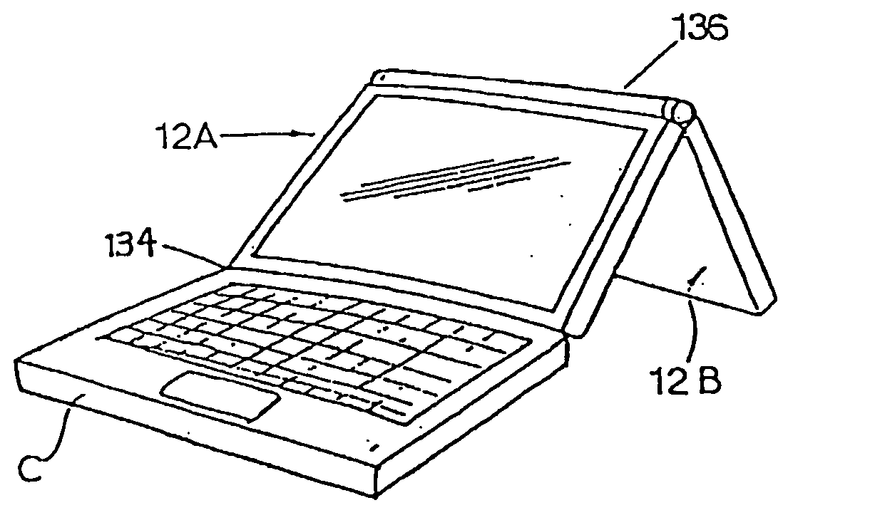
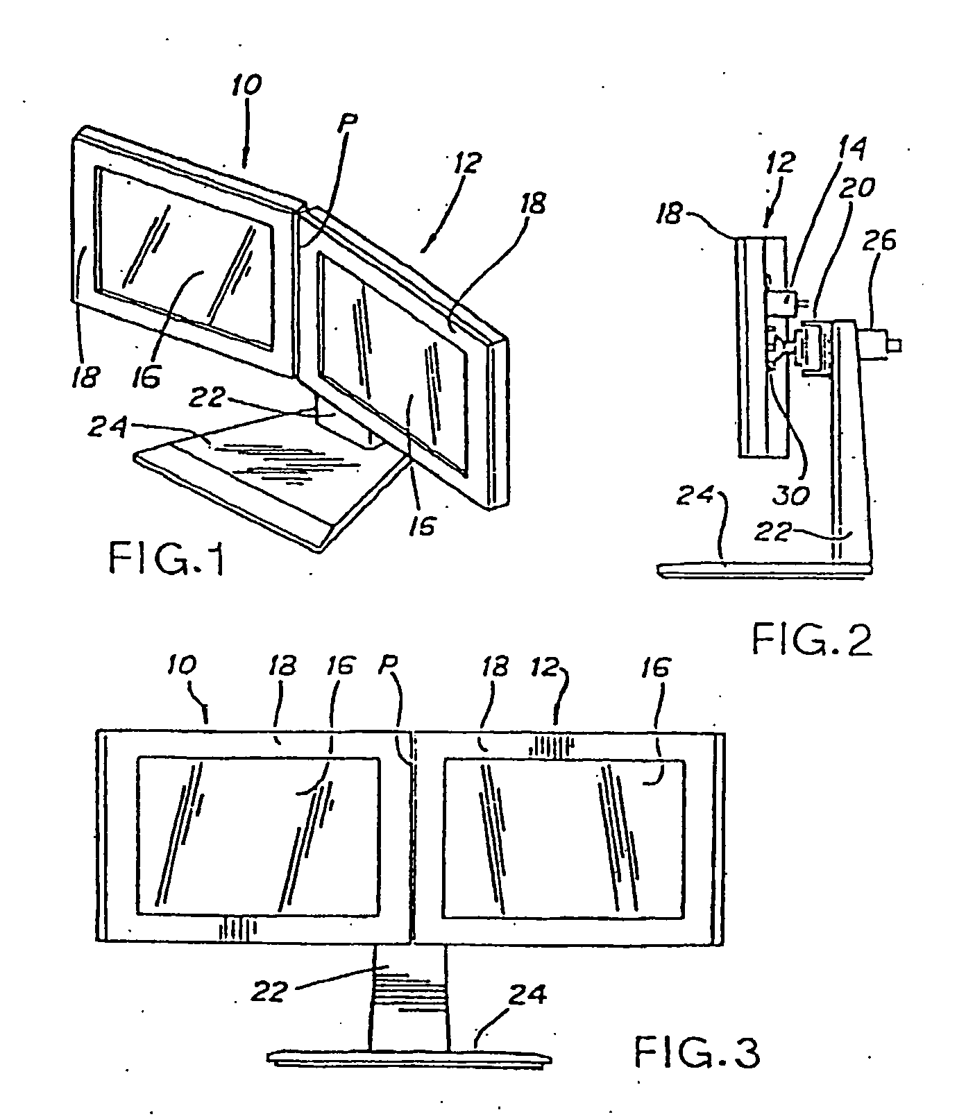
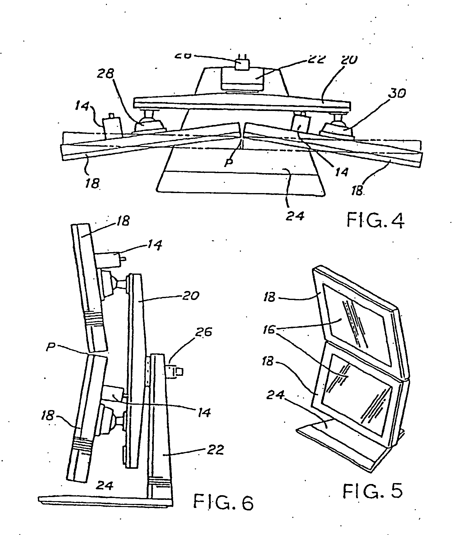
[0081] As already explained, the invention in this particular embodiment illustrated, has its application to the use of dual display screens, which can be used to display two different computer images simultaneously. This may have application for example in CAD computer design application. For these and other purposes it is particularly useful if the two screens or displays can be tilted towards one another so that they appear in the form more or less of two pages of an open book. The screens are preferably arranged side by side, in horizontal alignment, but may also be arranged vertically one above the other.

[0082] Referring now to FIGS. 1, 2 and 3, the invention is there illustrated as in the form of a pair of video display screens 10 and 12, each of which may be of known construction, but which may typically be liquid crystal displays (LCDs) for example. They are each provided with video terminal connectors 14 (FIG. 2) by means of which they may be connected to a computer.

[0083...


PUM


Abstract

An electronic display system is disclosed. The system includes a first display panel having a first viewing face and the second display panel have a second viewing face. The first and second display panels are coupled by a hinged mechanism which allows the angle between the first and second viewing faces to be greater than 180 degrees.

Description

TECHNICAL FIELD [0001] The invention relates generally to electronic displays having dual display screens used with computers and CAD design equipment, and more particularly to a display system permitting positioning of dual display screens in an infolded “booking” mode, and to a novel dismountable joint for mounting articles, such as display screens. Also disclosed is an interchangeable display screen and mounting. BACKGROUND OF THE INVENTION [0002] Computers are readily adapted to operate multiple displays. Paired monitors and screens are useful when large amounts of related information, such as data or graphics, must be compared. Paired monitors can be inconvenient, however, where limited desk space is available. Monitors may be horizontally aligned, or vertically aligned. It is especially desirable to permit swinging of the monitor orientations together into a “booking” mode. [0003] The invention also relates to a novel swingable mounting, which is suitable for mounting a variet...

Claims


Application Information

Patent Timeline
Patent Type & Authority Applications(United States)
IPC IPC(8): G06F1/16B60R11/00B60R11/02H04N5/64F16M11/04F16M11/12G09F9/00G09F9/35G09F9/40
CPCB60R11/02B60R11/0235B60R2011/0015F16M11/04F16M11/041F16M11/08F16M11/10F16M11/12F16M11/14F16M11/242F16M2200/022G06F1/1601G06F1/1616G06F1/1622G06F1/1624G06F1/1647G06F1/1649G06F1/1654G06F2200/1612
Inventor MOSCOVITCH, JERRY
Owner MOSCOVITCH JERRY
Why Eureka
Try Eureka