

Optical access network method, optical access network, and optical switch for optical access network
a technology of optical access network and optical switch, which is applied in the direction of multiplex system selection arrangement, multiplex communication, electrical equipment, etc., can solve the problems of reducing and affecting the service life of the optical access network. , to achieve the effect of reducing the loss, reducing the loss, and avoiding the loss of 3 db
- Summary
- Abstract
- Description
- Claims
- Application Information
AI Technical Summary
Benefits of technology
Problems solved by technology
Method used
Image

Examples
first embodiment
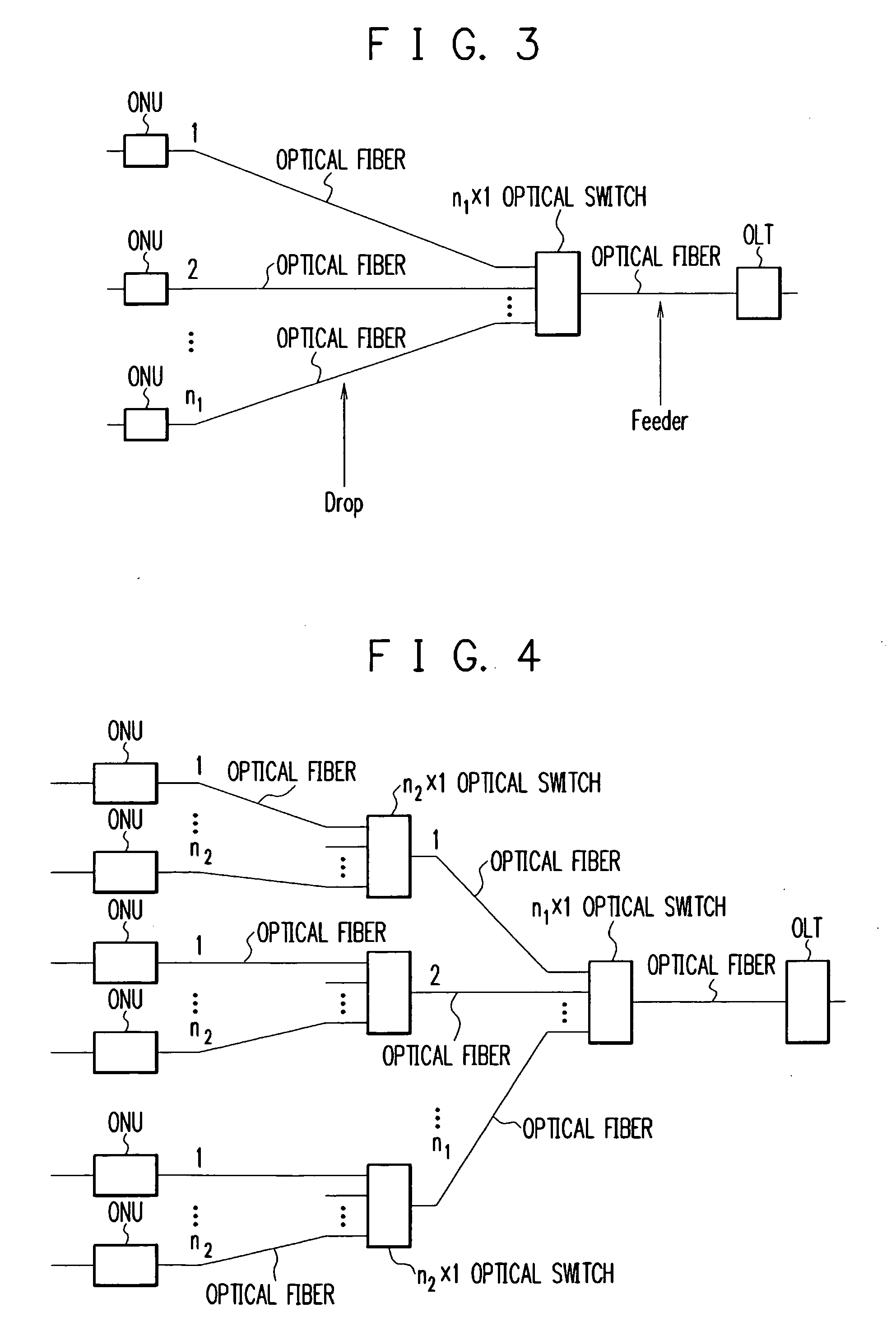
[0074]FIG. 3 is a diagram schematically showing the construction of an optical access network according to the first embodiment of the present invention. Referring to FIG. 3, the optical access network comprises an OLT (Optical Line Terminal), an n1×1 optical switch, and a plurality of ONUs (Optical Network Units). The 1 side of the n1×1 optical switch is connected through an optical fiber to the OLT. The n1 side of the n1×1 optical switch is connected through optical fibers to the ONUs. Based on a frame transmitted from the OLT to one of the ONUs, the optical switch automatically selects one ONU to connect it to the OLT with respect to uplink and downlink directions.
[0075] In other words, the optical switch connects a downlink frame only to the destination ONU of the frame, and not connects the frame to the other ONUs. Besides, the optical switch connects only the ONU that is arrowed to transmit an uplink frame to the OLT. To operate in the above manner, the optical switch may be ...
second embodiment
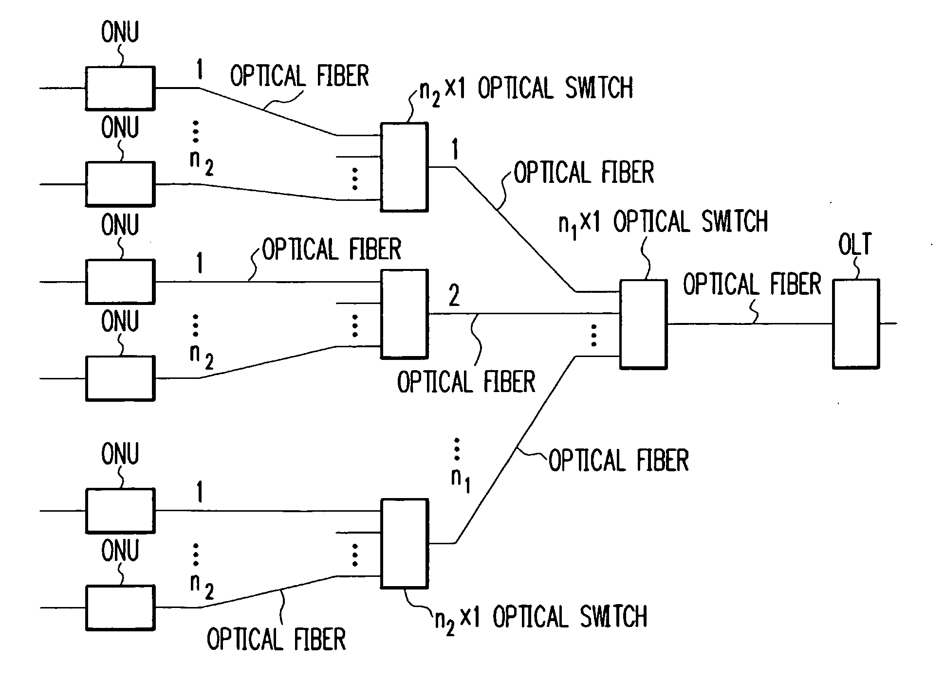
[0084]FIG. 4 is a diagram schematically showing the construction of an optical access network according to the second embodiment of the present invention. As can be seen in FIG. 4, the optical access network of this embodiment comprises an OLT, two stages of optical switches, and a plurality of ONUs. The OLT is connected through an optical fiber to the optical switch in the first stage. The optical switch in the first stage is connected through optical fibers to the optical switches in the second stage. The optical switches in the second stage are connected through optical fibers to the respective ONUs.
[0085] With two stages of relatively small optical switches: n1×1 optical switches with “n” being a small value, a larger optical switch can be implemented. Additionally, one optical fiber can accommodate a larger number of ONUs. In an n×1 optical switch, for example, if n=16, one optical fiber can accommodate 16×16=196 ONUs.
[0086] The transmission distance between the OLT and the O...
third embodiment
[0090]FIG. 5 is a diagram schematically showing the construction of an optical access network according to the third embodiment of the present invention. As can be seen in FIG. 5, the optical access network of this embodiment comprises an OLT, multistage optical switches, and a plurality of ONUs. The OLT and the ONUs are connected through a plurality of optical switches in a hierarchical (tree) structure. While the single-stage optical switch and the two-stage optical switches have been described in the first and second embodiments, respectively, the optical switches in the third embodiment are configured in the arbitrary number of stages. That is, the optical access network may include the arbitrary number of stages of optical switches in consideration of the number of ONUs to be accommodated, the transmission distance between the OLT and the ONU, the loss of each optical switch and the like. With this construction, all the three problems in the conventional technique can be solved...
PUM
 Abstract
Description
Claims
Application Information