Utilizing a laser to securely communicate with radio frequency identification tags

a radio frequency identification and laser technology, applied in the field of electronic systems, can solve the problems of limited electronic circuitry of rfid tags powered only by rf field energy, unintended parties may easily intercept information transmitted by rfid tags, and limited data storage space,

Inactive Publication Date: 2006-06-15
PITNEY BOWES INC
View PDF10 Cites 29 Cited by
  • Summary
  • Abstract
  • Description
  • Claims
  • Application Information

AI Technical Summary

Benefits of technology

[0008] This invention overcomes the disadvantages of the prior art by providing a secure communications channel for the transmission of a large amount of information between a RFID tag and a RFID reader. A laser beam is utilized to carry information and power from the RFID reader to the RFID tag. Thus, the laser beam has a dual use as an information carrier and a source of power for the RFID tag. Thus, only individuals and / or equipment that can both see the laser transmission and hear the RFID transmission can eavesdrop on the RFID tag RFID reader transmissions. This invention allows the use of complex algorithms to protect data being communicated, because they can use the increased level of power available to the RDIF tag. Additionally, more data can be stored in the tag. Additionally, using more sophisticated packaging can enhance the physical protection of stored data.
[0010] An advantage of this invention is that the RFID tag does not require a battery since it receives power from a laser beam.

Problems solved by technology

A disadvantage of the foregoing is that the information transmitted by the RFID tag may be intercepted easily and read by an unintended party.
As a result, the amount of electronic circuitry available in RFID tags powered only by the energy of RF fields is severely limited.
Furthermore, the complexity of algorithms to process data and the amount of data stored in such circuits are also very limited.
Thus, one of the disadvantages of the prior art is that RDIF tag circuits do not protect private information against sophisticated attackers.
Another disadvantage of the foregoing is that the amount of energy obtained by the RFID tags only from RF fields created by RFID readers is not sufficient to compute and analyze messages protected by strong cryptographic algorithms.
RFID tags using batteries are more expensive, bigger and have a limited life.
In addition to that, they may be less reliable as the battery may exhaust its energy during operation.

Method used


Image

  • Utilizing a laser to securely communicate with radio frequency identification tags
  • Utilizing a laser to securely communicate with radio frequency identification tags
  • Utilizing a laser to securely communicate with radio frequency identification tags

Examples


Embodiment Construction

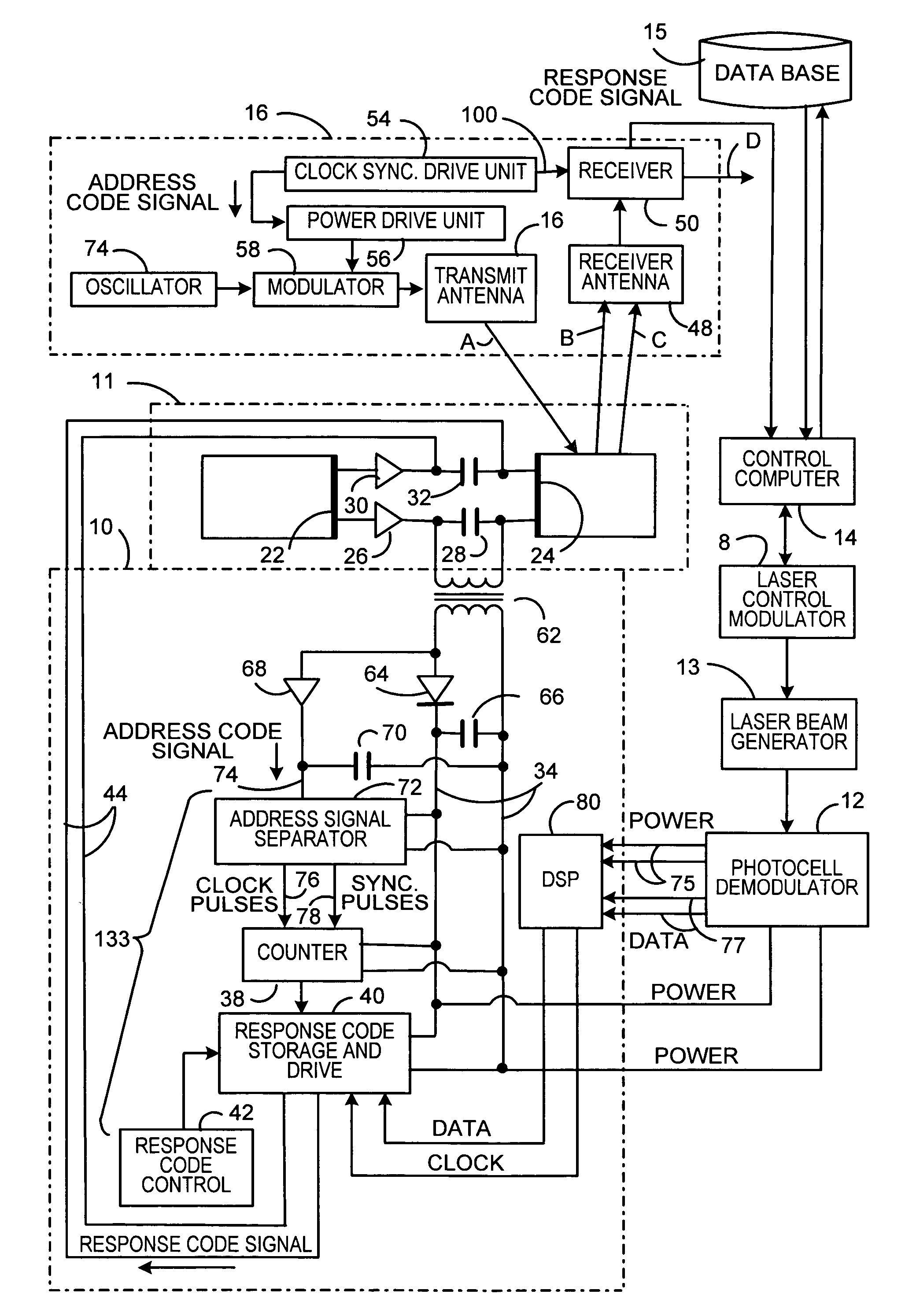
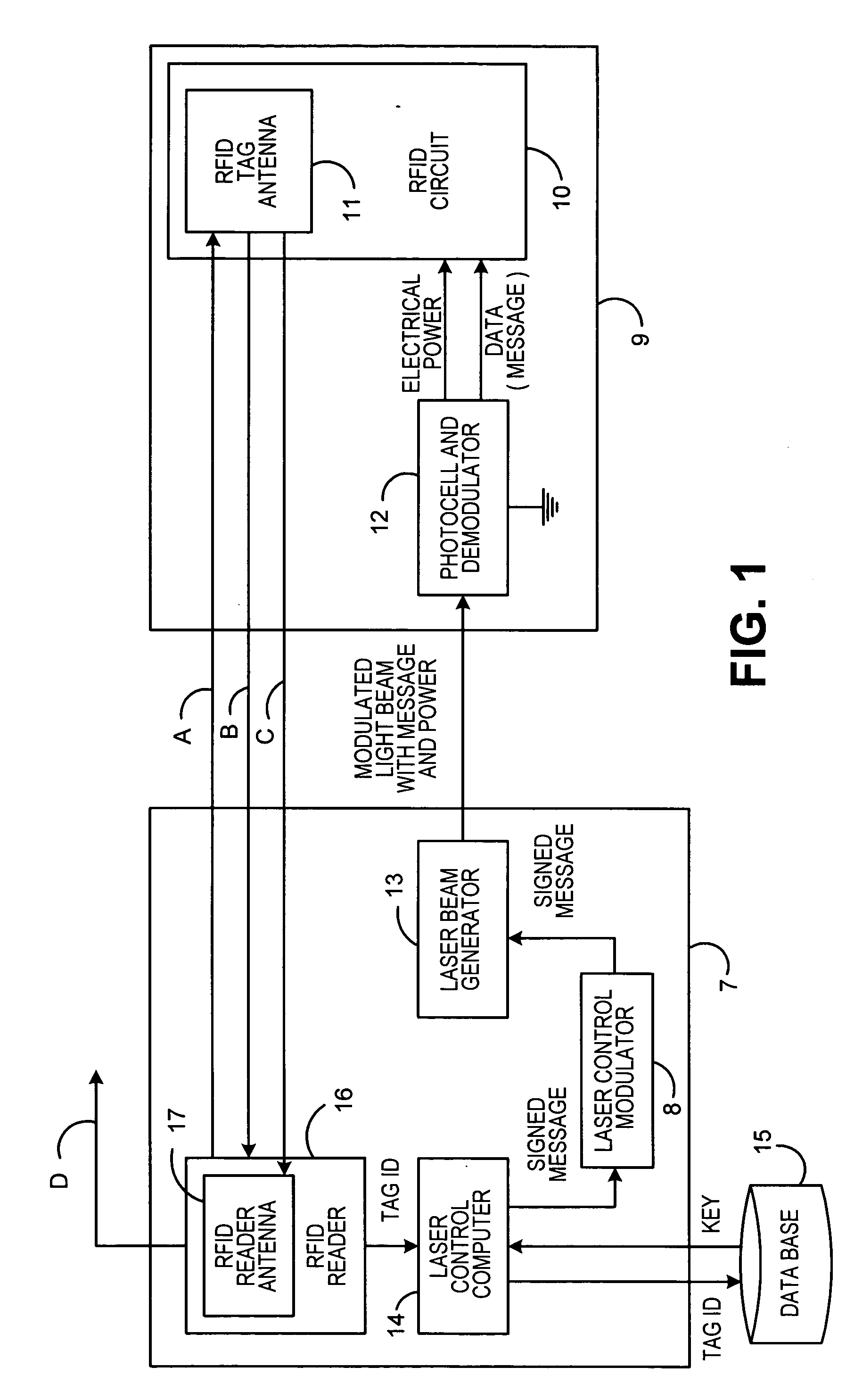
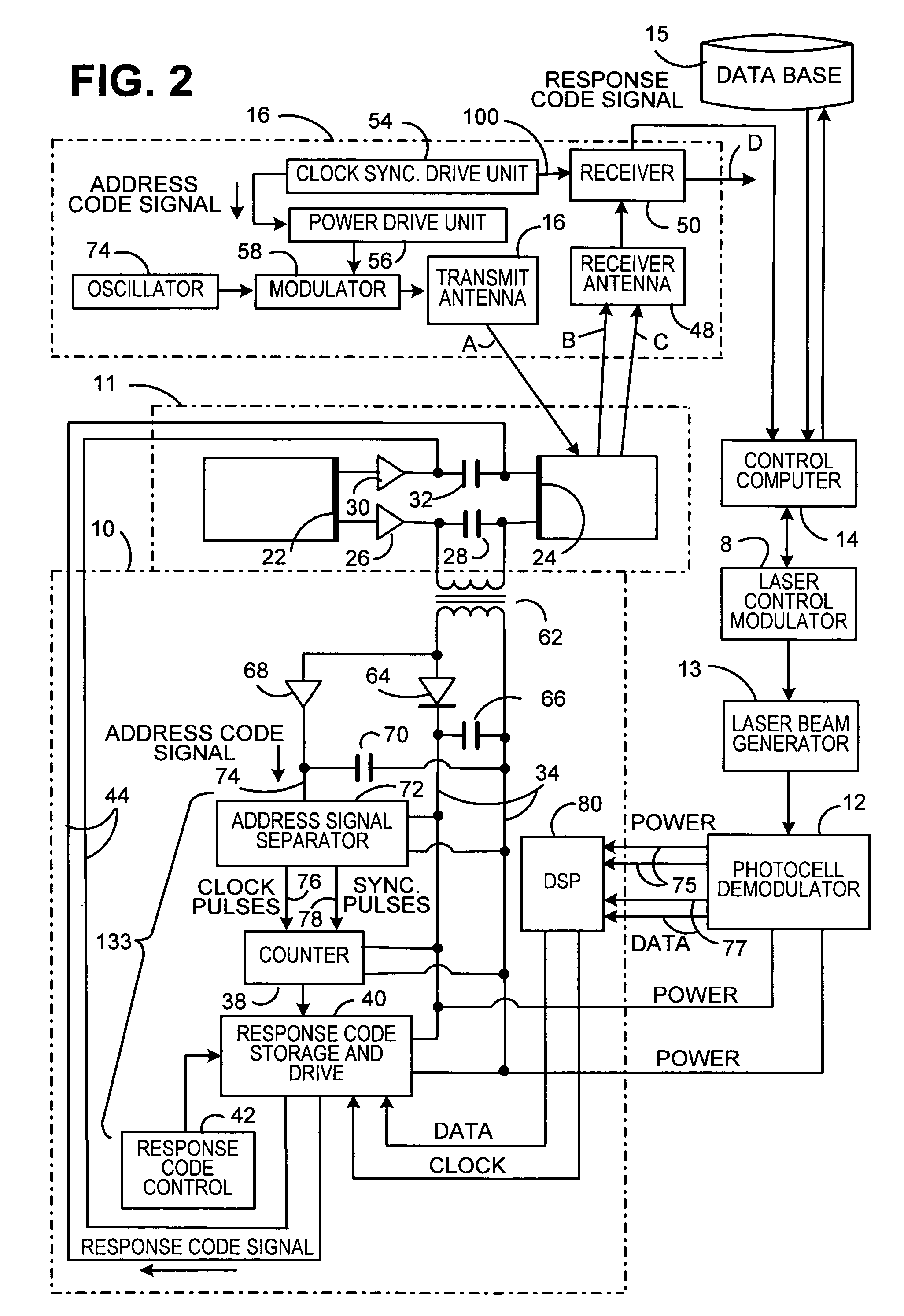
[0014] Referring now to the drawings in detail, and more particularly to FIG. 1, the reference character 9 represents a RFID tag. Tag 9 includes RFID circuit 10, which has a RFID tag antenna 11 attached thereto. RFID circuit 10 is coupled to photocell and demodulator 12. Demodulator and photocell 12 receives a light beam from laser beam generator 13. Generator 13 is coupled to modulator 8 and modulator 8 is coupled to laser control computer 14. Laser control computer 14 is coupled to data base 15 and computer 14 is also coupled to RFID reader 16, which has a RFID reader antenna 17 attached thereto. Computer 14, modulator 8 and generator 13 may be part of a bar code reader connected to the RFID reader 16. Computer 14, modulator 8, generator 13, reader 16 and antenna 17 comprise base station 7. Communications between RFID circuit 10 and RFID reader 16 would be performed as follows.

[0015] RFID reader 16 will cause RFID antenna 17 to transmit a radio frequency (RF) request signal via c...


PUM


Abstract

A method for providing a secure communications channel for the transmission of large amounts of information between a RFID tag and a RFID reader. A laser beam is utilized to carry information and power from the RFID reader to the RFID tag. Thus, the laser beam has a dual use as an information carrier and a source of power for the RFID tag. Thus, only individuals and / or equipment that can both see the laser transmission and hear the RFID transmission can eavesdrop on the RFID tag RFID reader transmissions. This invention allows the use of complex algorithms to protect data being communicated because they can use the increased level of power available to the RDIF tag.

Description

FIELD OF THE INVENTION [0001] This invention relates to electronic systems and, more particularly, to securely communicating with a radio frequency identification device that does not use batteries. BACKGROUND OF THE INVENTION [0002] Radio frequency identification device (RFID) tags have been programmed to contain digital information either during the manufacturing of the read-only memory portion of the RFID integrated circuit, or in the field using electromagnetic radio frequency signals to store information in the nonvolatile memory portion of the RFID tag. [0003] A RFID tag does not require contact or line-of-sight to operate. RFID tags can function under a variety of environmental conditions and provide a high level of data integrity. RFID tags utilize radio frequency signals to transfer information from the RFID tag to a RFID reader and from the RFID reader to the RFID tag. Thus, radio waves are used to transfer information between the RFID tag and the RFID reader from the RFID...

Claims


Application Information

Patent Timeline
Patent Type & Authority Applications(United States)
IPC IPC(8): H04B10/00
CPCG06K7/10336G06K19/0704G06K19/0723G06K19/0728H04B10/1141
Inventor OBREA, ANDREIFOTH, THOMAS J.
Owner PITNEY BOWES INC
Why Eureka
Try Eureka