Image forming apparatus
a technology of forming apparatus and forming sleeve, which is applied in the direction of electrographic process apparatus, instruments, optics, etc., can solve the problems of low perpendicular speed of the developing sleeve, and achieve the effect of suppressing fog
- Summary
- Abstract
- Description
- Claims
- Application Information
AI Technical Summary
Benefits of technology
Problems solved by technology
Method used
Image
Examples
embodiment 1
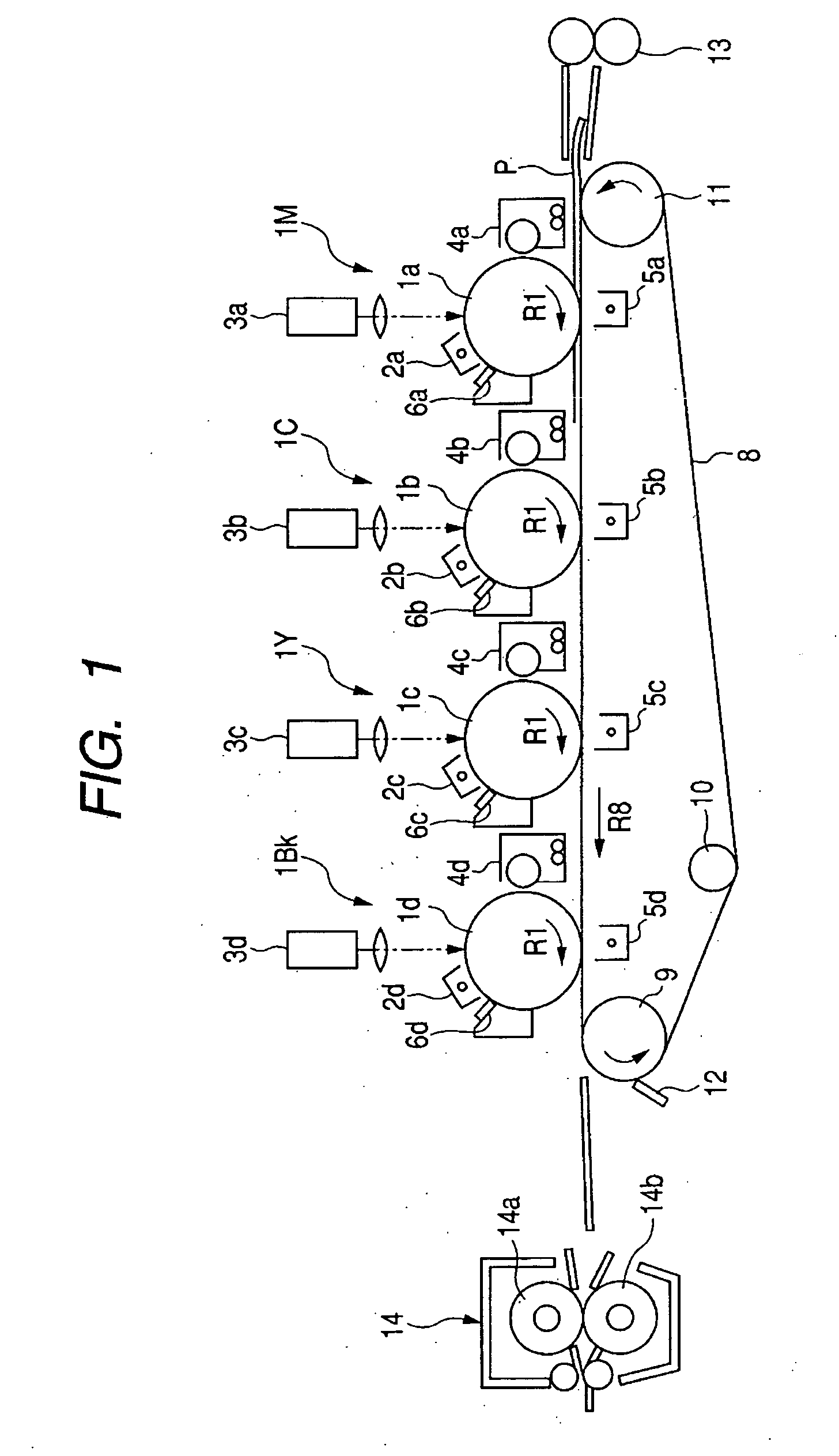
[0048]FIG. 1 shows an image forming apparatus to which the present invention can be applied. The image forming apparatus shown in FIG. 1 is a four color full-color printer having four image forming portions of an electrophotographic printing method, and FIG. 1 is a longitudinal cross-sectional view schematically showing the construction thereof.
[0049] The printer (hereinafter referred to as the “image forming apparatus”) shown in FIG. 1 has four image forming portions disposed along the movement direction (the direction indicated by the arrow R8) of a transfer belt 8, i.e., image forming portions 1M, 1C, 1Y and 1Bk for forming magenta (M), cyan (C), yellow (Y) and black (Bk) toner images, respectively, in succession from an upstream side.
[0050] Drum-shaped electrophotographic photosensitive members (hereinafter referred to as the photosensitive drums) 1a, 1b, 1c and 1d as image bearing members are disposed in the respective image forming portions 1M, 1C, 1Y and 1Bk for rotation in...
embodiment 2
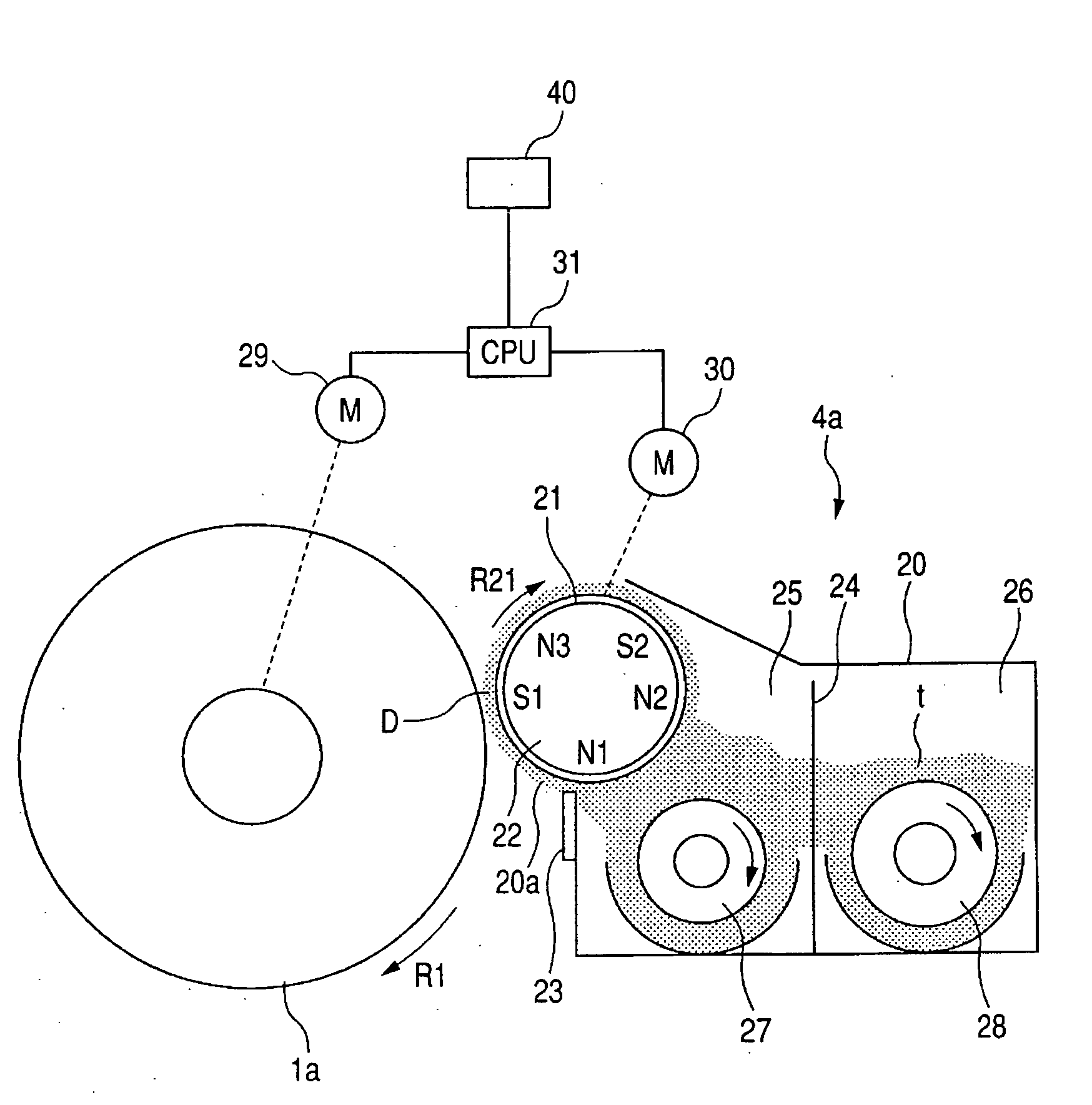
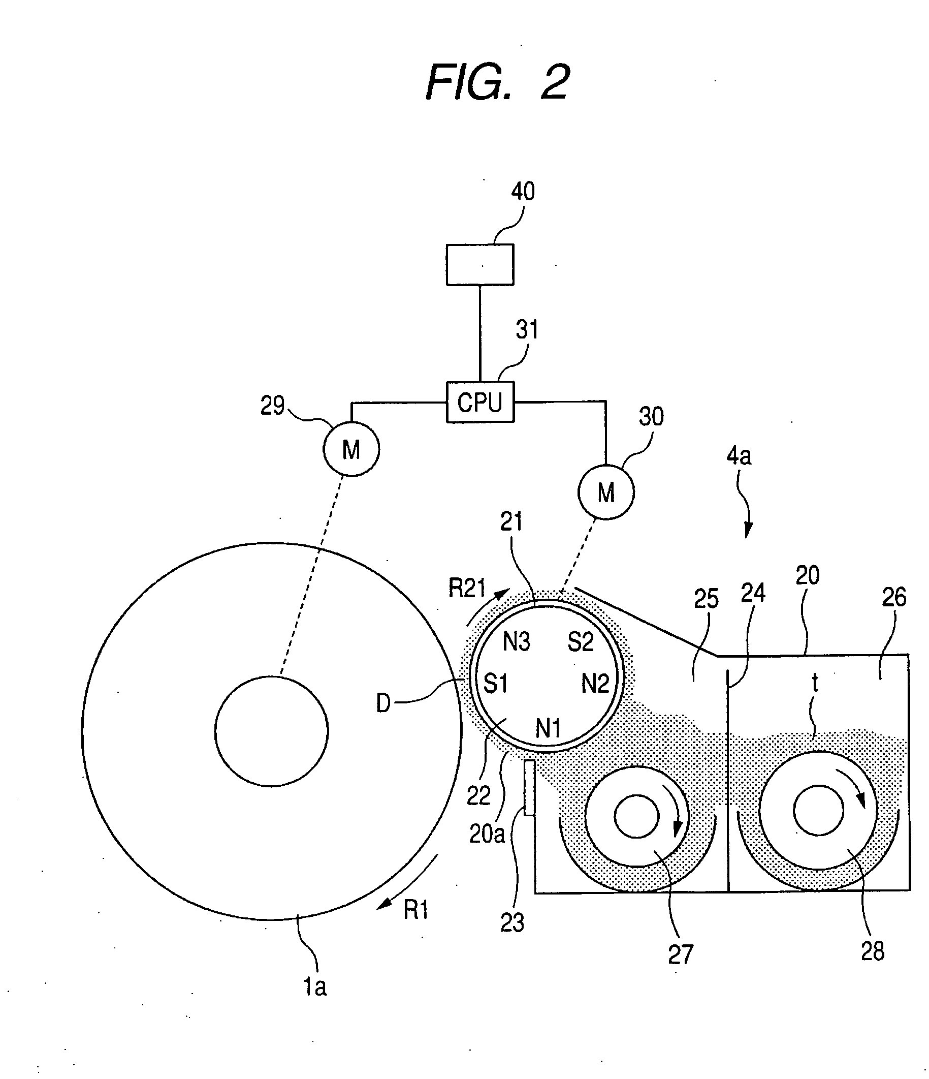
[0081] Embodiment 2 will now be described. The general constructions of an image forming apparatus and a developing apparatus according to this embodiment are similar to those of Embodiment 1 described above, but this embodiment is characterized in that at an image forming mode whereat the peripheral speed of the photosensitive drum becomes lower than that at a normal image forming mode, the peripheral speed ratio of the developing sleeve to the photosensitive drum is made variable in accordance with the period of use of the developer.
[0082] The charging amount distribution of the toner in the developing apparatus becomes such a distribution as indicated by solid line “a” in FIG. 8. The proportion of a toner of which the charging amount is in the vicinity of 0 (zero) or a toner charged to the opposite polarity is very low. However, when the period of use of the developer becomes long, the states of carrier particles and the developing sleeve on the side giving charges or the states...
embodiment 3
[0092] Embodiment 3 will now be described. The general construction of an image forming apparatus according to this embodiment is similar to that of Embodiments 1 and 2, but the present embodiment is characterized in that at an image forming mode such as the OHT mode whereat the peripheral speed of the photosensitive drum is made lower than at the normal image forming mode, the ratio of the peripheral speed of the agitating means to the peripheral speed of the developing sleeve is changed.
[0093] In the developing apparatus of an image forming apparatus, the developing sleeve and the agitating means are generally connected to the driving gear of an image forming apparatus main body through one and the same gear train, and the peripheral speed ratio between the two is fixed and therefore, when the peripheral speed of the developing sleeve is made high, the peripheral speed of the agitating means also becomes high. If in such a construction, as in Embodiments 1 and 2, at the image for...
PUM
 Abstract
Description
Claims
Application Information
 - R&D
- Intellectual Property
- Life Sciences
- Materials
- Tech Scout
- Unparalleled Data Quality
- Higher Quality Content
- 60% Fewer Hallucinations
Browse by: Latest US Patents, China's latest patents, Technical Efficacy Thesaurus, Application Domain, Technology Topic, Popular Technical Reports.
© 2025 PatSnap. All rights reserved.Legal|Privacy policy|Modern Slavery Act Transparency Statement|Sitemap|About US| Contact US: help@patsnap.com


