
Vein Stabilizer

a technology of stabilizer and vein, which is applied in the field of vein stabilizer, can solve the problems of easy roll, easy to roll, and difficult to find veins and stabilize,

Inactive Publication Date: 2006-06-15
PETERS PAUL
View PDF9 Cites 13 Cited by
  • Summary
  • Abstract
  • Description
  • Claims
  • Application Information

AI Technical Summary

Benefits of technology

The vein stabilizer is a small device that helps to make the vein appear more visible and stable during a medical procedure. It does this by isolating the vein and making it roll less when it is punctured. This makes it easier for the medical professionals to find and access the vein.

Problems solved by technology

The technical problem addressed in this patent text is the difficulty and pain associated with finding and stabilizing veins in order to inject a needle or draw blood. This process can be time-consuming and frustrating for nurses, and patients often experience discomfort from delayed IV lines. The patent aims to provide a solution to establish a prominent vein for IV needle introduction in a minimum amount of time, regardless of the patient's status or condition.

Method used


Image

  • Vein Stabilizer
  • Vein Stabilizer
  • Vein Stabilizer

Examples


Embodiment Construction

[0024] In describing a preferred embodiment of the invention illustrated in the drawings, specific terminology will be resorted to for the sake of clarity. However, the invention is not intended to be limited to the specific terms so selected, and it is to be understood that each specific term includes all technical equivalents which operate in a similar manner to accomplish a similar purpose.

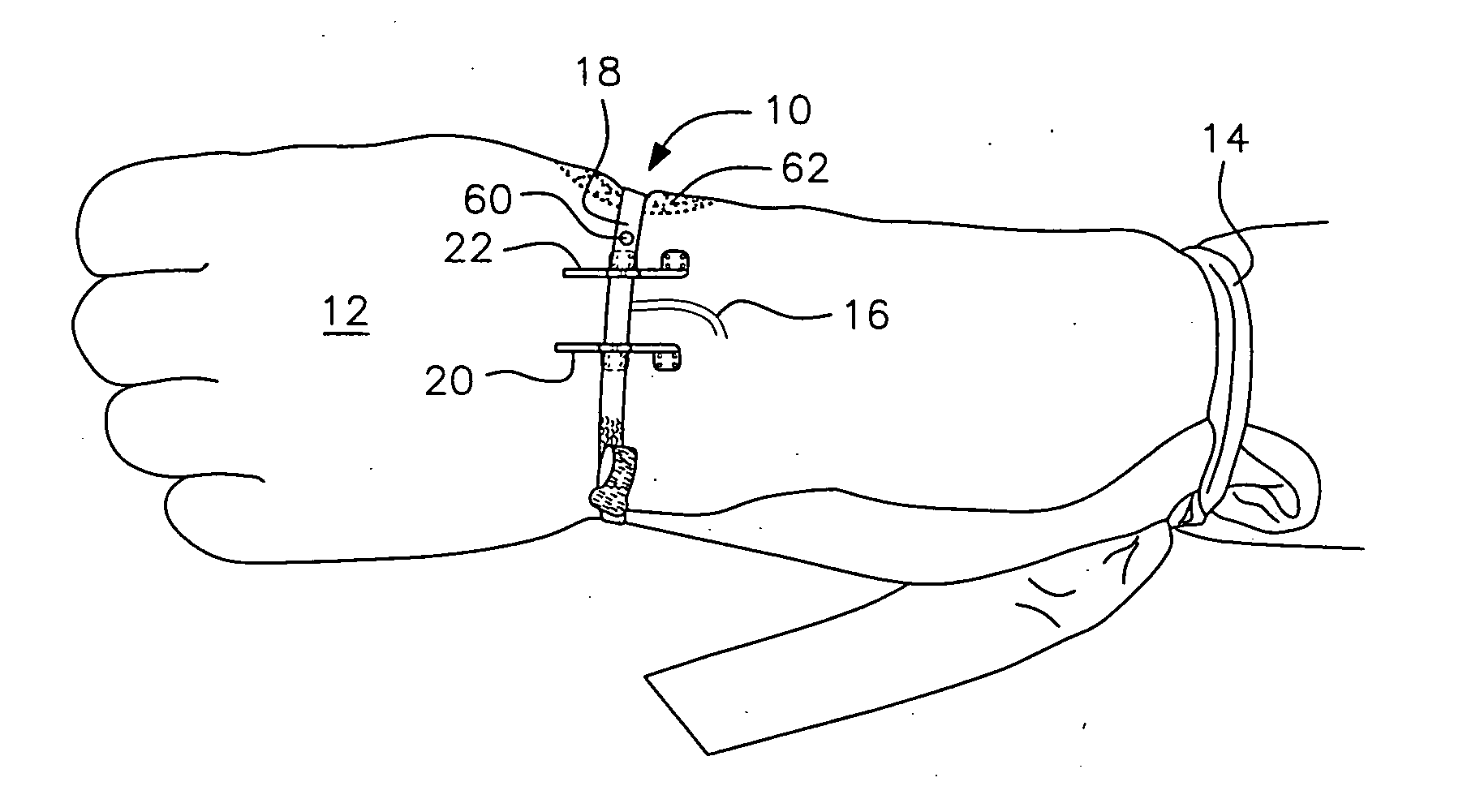
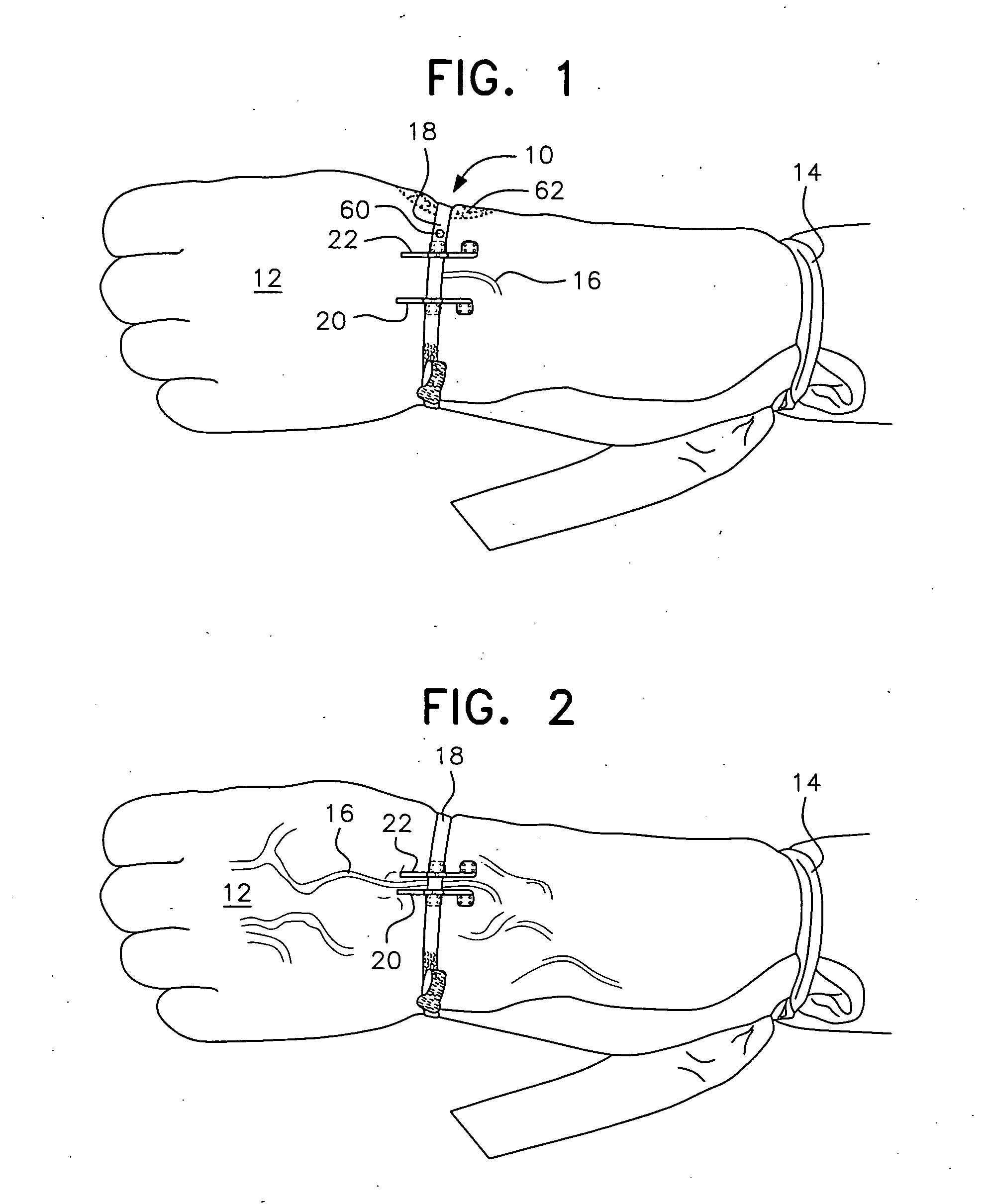
[0025] With reference to the drawings, in general, and to FIGS. 1 and 2, in particular, the vein stabilizer embodying the teachings of the subject invention is designated as 10. With reference to its orientation in FIG. 1, the vein stabilizer is shown mounted on the hand 12 of a patient. A tourniquet 14 has been placed on the forearm to help in locating a vein 16 which needs to be pierced to initiate transfer of an intravenous solution or other medication.

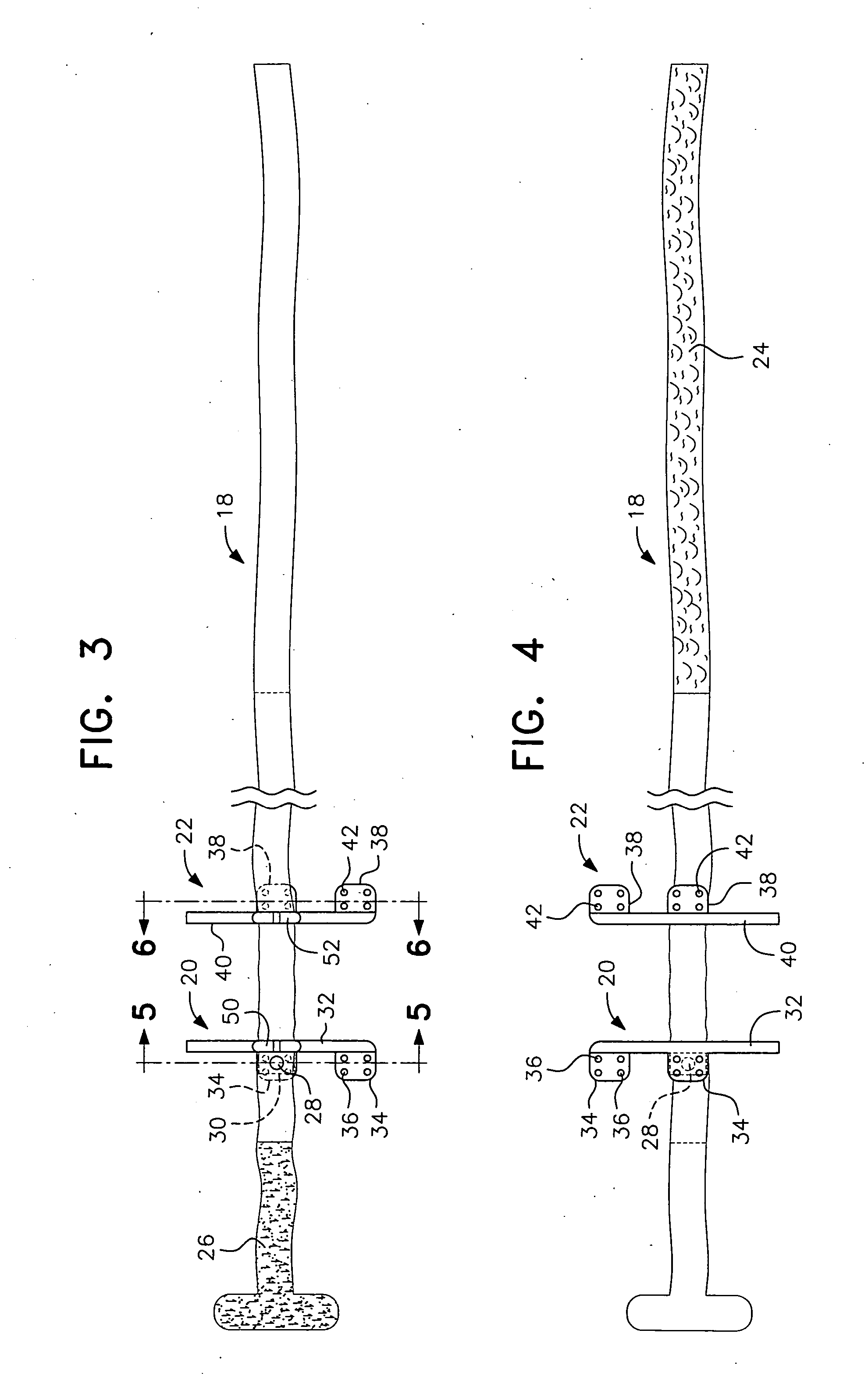
[0026] The vein stabilizer includes an elongated strap 18 and two tabs 20, 22. Tab 20 is fixed on the strap 18, whereas tab 22 is slidably ...


PUM


Abstract

The vein stabilizer is a small device that: 1) isolates the vein, so it cannot roll from side to side when penetrated; and 2) causes the vein to bulge toward the surface of the skin making it more apparent. The vein stabilizer includes a sterile, two-piece disposable plastic device that isolates the vein in between two plastic tabs which are similar in shape and size. One tab is fixed on the skin on one side close to the vein. The other piece is mobile and slides on an elastic band. The tabs are adjusted to the preference of the IV initiator or the situation on the other side of the vein (big vein, small vein, tortuous vein, collapsed vein, sclerous (hardened) vein, obese patient, etc.).

Description


Claims


Application Information

Patent Timeline
Owner PETERS PAUL
Learn More